What is a multimeter and what characteristics are important when choosing it

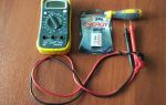
When creating or repairing electrical circuits, various measuring instruments are used that allow you to monitor all the necessary parameters. A multimeter is a universal device that combines at least three of them - a voltmeter, an ammeter and an ohmmeter, to measure voltage, current and resistance, respectively. This already allows you to get a significant amount of information about the electrical circuit both in working condition and when the power is off.
Content
What are the multimeters
Different generations of electricians can each explain in their own way what a multimeter is, since these devices are being improved all the time. Some people think that this is a rather large and heavy box, while others are used to miniature devices that fit easily in the palm of your hand.
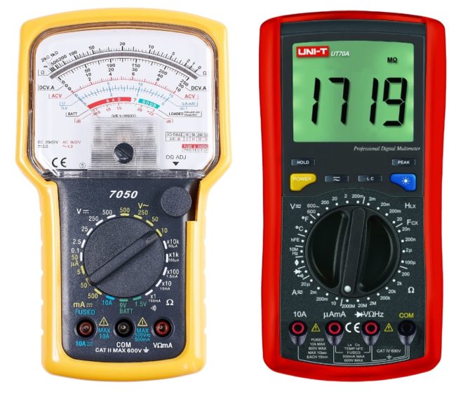
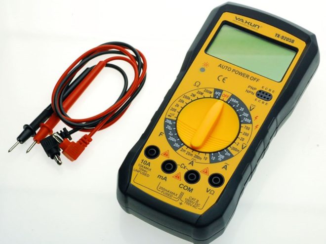
First of all, all multimeters are divided into devices according to the principle of operation - they are analog and digital. They are easy to distinguish by their appearance - analog dials have a dial, and digital ones have a liquid crystal display. It is quite simple to make a choice between them - digital ones are the next stage in the development of these devices and outperform analog ones in most indicators.
When the first digital multimeters appeared, they, of course, had certain design flaws, allowing us to say that this is a toy for amateurs, but even then it was clear that digital devices have huge potential and over time they will replace analog devices.
Analog multimeters
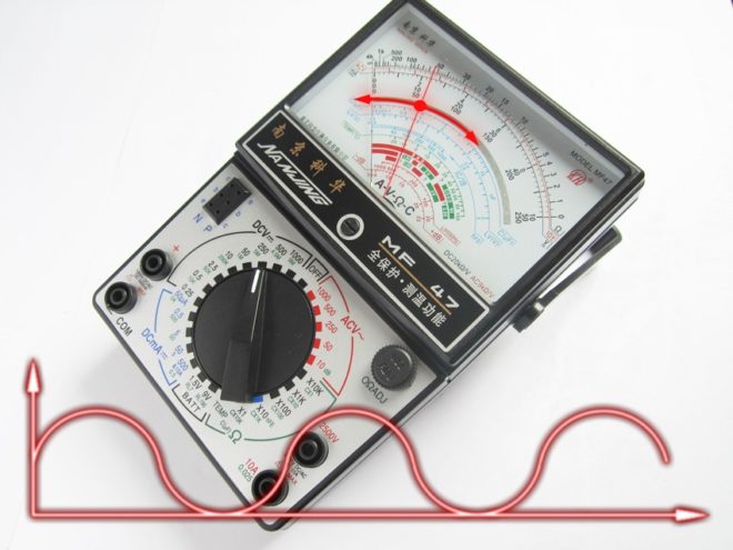
In some cases, the use of analog multimeters is justified even now - they still have a number of advantages that are due to the very design of the measuring device. Its main part is a frame with an arrow attached to it. The frame can be rotated from the effect of an electromagnetic field on it - the stronger it is, the greater the angle of rotation.
Based on this, the main advantage of the analog device is highlighted - the inertia of the display of measurement results.
In simple words, this is displayed in the following properties:
- If it is necessary to measure not linear, but variable data (V, A or Ω), then the arrow in real time will show their changes, clearly demonstrating the entire amplitude of signal oscillations. H, "digit" in this case, the result will be shown stepwise - its value will change every 2-3 seconds (it depends on the sensitivity of the device and its data processing speed).
- The pointer multimeter is able to detect stray voltage or current ripple. For example, if there is a constant current in the circuit with a value of one ampere, but every few seconds it can briefly increase / decrease by 1/10 or 1/5, and then return to the rating. In this case, the digital tester may not show any signal changes at all, and the analog arrow will at least "shake" at these moments. The same will happen in the presence of persistent interference - if the voltage fluctuations are already noticeable - the digital multimeter will constantly show various data, and the analog one is just some averaged - "integrated" value.
- To operate a digital multimeter, a power source is required, and an analog battery is only needed if you turn on the ohmmeter mode.
- There may be different extreme conditions for different devices.If digital without proper protection cannot work, for example, in a high-frequency electric field, then for analog ones this is not a serious test - they can even serve as indicators of its presence.
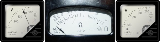
All of the above applies not only to multimeters, but also to each analog measuring device separately - an ammeter, voltmeter or ohmmeter.
Digital multimeters
Their main trump card is simplicity and functionality, which are reflected in the distinctive properties of such devices:
- For the manufacture of such a device, it is not necessary to carry out filigree work on the manufacture of electromagnetic coils and their fixing in the case, debugging and subsequent adjustment already during operation.
A digital multimeter is simply an electrical board into which contacts and control elements are soldered.
- The values displayed on the screen do not require "decoding" or interpretation, which is often the case with analog devices, the readings of which may not be understood by a layman.
- Vibration resistant. If shaking simply has the same effect on digital devices as on any part, then it affects the analog arrow very noticeably, and in some cases can lead to damage to the device.
- Unlike analog devices, a digital multimeter calibrates itself every time it is turned on, so there is no need to constantly set zero on the dial, which is a disease of any dial gauge.
This is not the whole list of possible advantages of a digital multimeter - only those that clearly distinguish it from an analog device.
As a result, if you are serious enough to engage in electrical work, then it is desirable to have devices of both types in your arsenal, since some of their capabilities are diametrically opposite.
How measurements are taken with digital and analog devices - in the following video:
What can be measured with a multimeter
The very first analog devices combined 3 instruments in one and they could check voltage (V), current (A) and resistance values of conductors. At the same time, if there was no particular problem in measuring the voltage for direct and alternating currents, then it was not immediately possible to combine measuring instruments for checking the current strength - both direct and alternating - in one case. It would seem, what does the matter of bygone days have to do with it, but the fact is that not all budget devices still include such functionality. As a result, the mandatory minimum, which includes a multimeter today, is a voltmeter for alternating and direct currents, measuring resistance and strength of alternating or direct current.
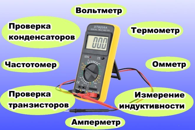
Further, based on the class of the device, in addition to the voltmeter, ammeter and ohmmeter, it can also contain frequency and temperature meters, circuits for testing diodes (often combined with an audio signal - very convenient for use as a regular dialing), transistors, capacitors and other functions.
Not everyone and not always needs all of the listed functions, so the choice of such a device is an individual task, which is solved based on the planned front of work and the budget that can be allocated for the purchase of the device.
Legend on the scale and front panel of the multimeter
It is not necessary to read the instructions for the multimeter to determine what it is capable of - this information will be available if you just look at its front part with a scale for setting the modes of use.
Since the functionality of analog devices is less than that of digital ones, the last device should be considered as an example.
On the overwhelming majority of models, the modes are set by means of a rotary dial, which has a mark indicating the section of the scale applied to the case.
The scale itself is divided into sectors, the labels in which visually differ in color or are visually divided into zones. Each of them designates a parameter that the tester measures and allows you to set its sensitivity.
Overview of the functionality of the digital tester on video:
DC and AC
The ability of the device to measure AC and DC current values is visible by graphic labels or letter designations. Since the overwhelming majority of testers are produced by foreign manufacturers, they are also labeled in Latin letters.

Alternating current is a wavy line or the letters "AC", which stand for "Alternating current". Constant, in turn, is marked with two horizontal lines, the upper one is solid, and the lower one is dotted. The letter designation is written as DC, which stands for "Direct Current". These marks are placed near the sectors that include the modes for measuring current strength (denoted by the letter "A" - Ampere) or voltage (denoted by the letter "V" - Volt). Accordingly, for constant voltage, the designations will look like the letter V with dashes next to it or the letters DCV. AC voltage is indicated by the letter V with a wavy line or the letters ACV.
Sectors for measuring current strength are similarly marked - if it is variable, then this is the letter A with a wavy line or ACA, and if it is constant, then the letter A with dashes or letters ADA.
Metric prefixes and measuring ranges
The sensitivity of the device can be configured to measure not only whole units, because often hundredths or even thousandths of a Volt or Ampere are used in electrical circuits.
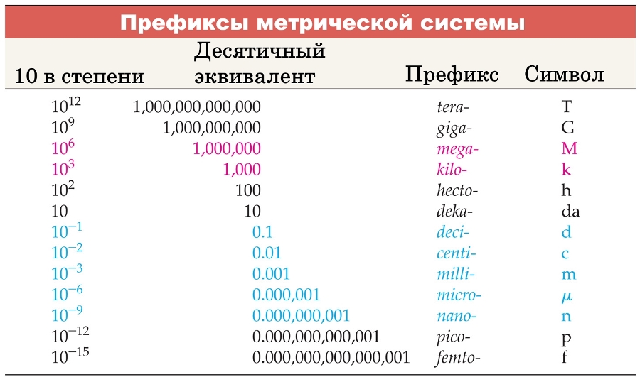
For the correct display of the results, the circuit provides switches for shunts of various resistances and the device shows integer values taking into account the following prefixes:
- 1µ (micro) - (1 * 10-6 = 0.000001 from one)
- 1m (milli) - (1 * 10-3 = 0.001 from one)
- 1k (kilo) - (1 * 103 = 1000 units)
- 1M (mega) - (1 * 106 = 1,000,000 units)
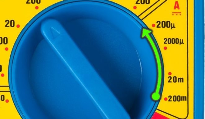
If the device is set to measure direct current (DCA) - the pointer, for example, is turned to 200 mA, this means:
- The maximum current that can be measured in this position is 0.2 Ampere. If the measured value is greater, then the device will show an overshoot.
- 1 unit shown by the tester equals 0.001 Ampere. Accordingly, if the device shows a figure, for example, 53, then this should be read as a current of 53 milliamperes, which in fractional decimal notation will look like 0.053 amperes. In the same way, the prefix "kilo" and "mega" is used - if the regulator is set to them, then the unit on the device display means a thousand or a million (these prefixes are mainly used when measuring resistance).
If the device shows a unit, then for the measurement accuracy it is worth trying to reduce the range - instead of the value on the scale with the “m” prefix, set a digit with the “µ” prefix.
Symbols for various functions
Other functions of the multimeter can also be identified with different symbols or letters. At the same time, when evaluating the functionality of the device, one must remember that the symbols on the multimeter can refer to different sectors and carefully look at each icon:
- 01. Display backlight - Light
- 02. DC-AC - this switch "tells" the device what current will be measured - direct (DC) or alternating (AC).
- 03. Hold - the key for fixing the last measurement result on the screen. Mostly this function is in demand if the multimeter is combined with a measuring clamp.
- 04. The switch tells the device what will be measured - inductance (Lx) or capacitance (Cx).
- 05. Power on. In many models, there is no testers - instead, the power turns off the translation of the pointer to the uppermost position - "at 12 o'clock"
- 06. hFE - socket for testing transistors.
- 07. Sector Lx, to select the limits of measurement of inductance.
- 08. Temp (C) - temperature measurement. To use this function, an external temperature sensor must be connected to the device.
- 09. hFE - enable the transistor test function.

- 10. Enabling diode test.Often this function is combined with a sound signal for continuity of the electrical circuit - if the wire is intact, then the tester "beeps".
- 11. Sound signal - in this case it is combined with the lowest resistance measurement limit.
- 12. Ω - When the switch is in this sector, the device operates in ohmmeter mode.
- 13. Sector Cx - capacitor test mode.
- 14. Sector A - ammeter mode. The device is connected to the circuit in series. In this case, the sector itself is aligned for direct or alternating currents, and which of them is measured depends on the switch "2".
- 15. Fric (Hz) - function of measuring the frequency of alternating current - from 1 to 20000 Hertz.
- 16. Sector V - to select the limits for measuring the voltage of the electric current. In this case, the sector itself is aligned for direct or alternating currents, and which of them is measured depends on the switch "2".
In addition to the rotary knob, the multimeter has sockets for connecting probes - they are used by the master to touch the points at which readings need to be taken.
Depending on the model of the multimeter, there can be 3 or 4 such jacks.
- 17. The red probe is connected here, if necessary, measure the current strength up to 10 Amperes.
- 18. Socket for the red probe. It is used when measuring temperature (the switch at this time is set to division 8), current up to 200 mA (switch in sector 14) or inductance (switch in sector 7).
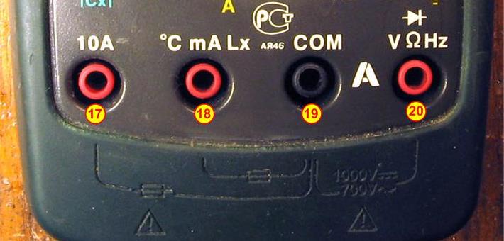
- 19. "Ground", "minus", "common" wire - a black probe is connected to this terminal.
- 20. Socket for a red probe when measuring the voltage of an electric current, its frequency and resistance of the wiring (plus continuity).
Conclusion - what to choose
It is difficult for a professional electrician to advise what functionality he needs from a multimeter to work, and even more so there is no point in recommending any particular model of the device - everyone will select a device, or even several, to suit their needs. Well, for home use, oddly enough, it is better to take a device close to the "fancy" one, but within reasonable limits in terms of cost. More on video:
The fact is that in this case it is difficult to predict which of the functions may come in handy over time. At a minimum, you will definitely need a continuity and a voltmeter, and if it becomes necessary to check the power of any device, then an ammeter. Further, in descending order, you can arrange the check of temperature, capacitors, transistors, field strength and frequency of the electric current. In addition to the thermometer, these are all specific functions that are of interest only to fans of radio electronics, but for an ordinary layman they will simply increase the cost of the device.