How to check an RCD yourself - four easy ways

The most unpleasant thing that can happen to the protective automatics of the electrical circuit is that it will not work at the right time. To prevent this from happening, all devices are repeatedly tested, and this is done not only during manufacture, but also during operation - this can be done at home. At the same time, if everyone is already accustomed to the circuit breakers and the principle of their operation, then how to check the RCD - how ready it is for an emergency situation - often remains a mystery for an inexperienced user in electrical engineering.
Content
Principle of RCD performance check
When a material is tested for strength, attempts are made to break it. To test protective devices, it is necessary to create conditions under which they will work - according to these rules, all existing checks are carried out.
The residual current device trips if it detects a leakage current, i.e. when more current is supplied to the electrical circuit through the phase wire than it exits through the zero. The RCD connection can be performed in houses with and without grounding - to carry out checks, you need to understand the difference between these methods of protecting household appliances and a person.
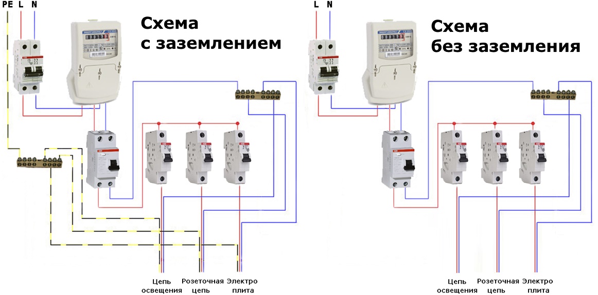
- In the first case, if the insulation of the wiring is broken, then part of the current goes to the body of the electrical appliance, from where it will immediately go to the ground wire, as a result of which a leak occurs, which the residual current device immediately registers and opens the circuit.
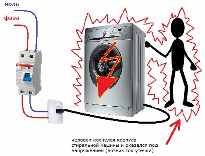
- If there is no grounding, then if the insulation is damaged, the current again enters the body of the electrical appliance, but since there is nowhere for it to go further, then, in general, the balance between the input-output is maintained and the RCD does not work yet. A leak will be detected only if a person touches a faulty electrical appliance - a current will flow through the body, the balance between the incoming and outgoing current in the main circuit will be violated and the RCD will immediately turn off the power.
Those. a properly connected and serviceable residual current device will work in any case, but if the network is not grounded, then the malfunction will be detected only after the person is slightly tickled with current (if the device is correctly selected, then even painful sensations should not arise).
Of course, if there is no grounding, then checking the operation of the RCD by touching the phase wire is, to put it mildly, a very extreme way - if suddenly the device is faulty, then a noticeable electric shock is inevitable.
Despite the difference in the connection methods, the principle of operation of the residual current device remains unchanged and all methods for checking the device are suitable in both cases. At the same time, the installed difavtomat is checked in the same way, because this is the same RCD, only combined in the same case with a circuit breaker.
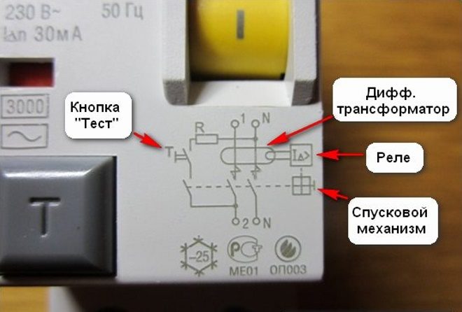
Test button - built-in leakage current simulator
On the front panel of each residual current device there is a button with the letter "T" or the inscription "Test". This is the easiest way to quickly check the RCD - when this button is pressed, an additional capacitance or resistance appears in the electrical circuit, where part of the current goes. A leakage current is generated which will cause the residual current device to trip.
With the obvious usefulness of this function, it must be understood that the "Test" button on the RCD itself is not a panacea and its operation or non-operation does not provide complete information about the state of the device. The options here can be as follows:
- If the RCD does not work, but at the same time it is only connected, then in addition to a malfunction, this may indicate an incorrect installation of the device itself. In this case, first of all, you need to double-check the connection diagram.
- If earlier the button worked, but now it does not - in this case, a more thorough check of the RCD and its connection diagram is necessary.
- The "Test" button itself does not work, but the residual current device is generally working. This is checked only by additional methods, but in any case, the device is defective and it is strongly recommended to replace it.
- Additional methods of checks confirm that the device itself is faulty - here there is no way to replace the device.
Checking the RCD with the "Test" button should be carried out regularly - about once a month, and by more advanced methods at least once a year.
Battery test
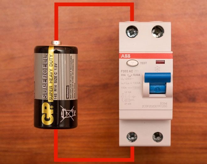
Testing an RCD with a battery is one of the safest test methods - there is no need to wait until the leakage current appears, but conditions are created under which the RCD “thinks” that it has arisen. In addition, the current generated by the battery is not felt by humans.
The point is to pass current only through one of the coils of the device - it will not be on the second one and the internal "calculator" of the device will give a command to open the circuit. By the way, in this way you can easily check the performance of the RCD upon purchase.
In practice, it looks like this:
- If the residual current device is already connected to the network, then first it is disconnected from all wires.
- Short wires are connected to one of the poles of the device (left or right terminals above and below) (so that they can touch the battery).
- The ends of the wires (stripped of insulation) touch the plus and minus of the battery - a current will flow through one of the coils of the device and if the RCD is working properly, the protection will work.
The following video demonstrates the use of this method:
There are three main points to consider when checking this:
- The current provided by the battery must be at least equal to, or better, exceed the current setting of the device - if the latter is 100mA, and the battery produces 50, then no operation will occur.
- It is likely that the polarity will have to be observed - if after touching the battery terminals, no operation occurs, then you need to change the plus and minus places. If operation does not occur again, then this is already a malfunction indicator or an electronic residual current device purchased.
Read more about the difference in checking electronic and electromechanical RCDs in the video:
Checking the operation of the RCD with a control lamp
In this case, a leakage current is directly created from the circuit, which is protected by the RCD. For the correct test, it is necessary to understand here whether there is a grounding in the circuit or the residual current device is connected without it.
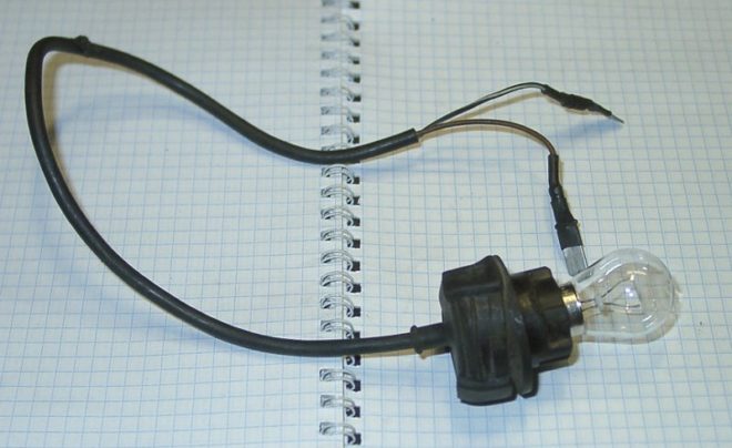
To assemble the control, you will need the light bulb itself, a socket for it and two wires. In fact, a carrying lamp is going to be assembled, but instead of a plug, there are bare wires that can touch the contacts being tested.
Nuances of assembly control
When assembling the control, two important nuances must be taken into account:
- First, the lamp must be powerful enough to generate the required leakage current. If a standard RCD with a setting of 30 mA is checked, then there are no problems - even a 10-watt light bulb will take a current of at least 45 mA from the network (calculated by the formula I = P / U => 10/220 = 0.045).
Attention should be paid to this point in the case when the setting of the residual current device is about 100 mA - then you need to take a light bulb with a power of at least 25 watts.
- Secondly - if you take a light bulb that is too powerful. If the only question is how to check the RCD for operation, then you can ignore this moment.If, however, it is additionally necessary to assess whether the setting value has not been calibrated, then the circuit will have to be supplemented. For example, if you assemble a control with a 100 watt light bulb, then the current strength on it will be about 450 mA. At the same time, it is not known at what current the residual current device worked - if it still calibrated and works instead of 30 at a current of 100 mA, then a person can receive a fatal electric shock. To test the RCD for operation at rated current, a resistance must be added to the control, which will reduce the current in the circuit to the required one.
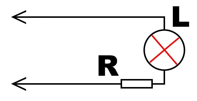
Important!!! In this case, the resistance of the light bulb itself must be calculated, and not measured with a multimeter, since the resistance of a cold tungsten filament is about 10-12 times less than that of a hot one.
Calculation of control resistance
Ohm's law will help to calculate the required resistance - R = U / I. If we take a 100-watt light bulb to test a residual current device with a setting of 30 mA, then the calculation procedure is as follows:
- The voltage in the network is measured (for calculations, the nominal value of 220 volts is taken, but in practice, plus or minus 10 volts can play a role).
- The total resistance of the circuit at a voltage of 220 Volts and a current of 30 mA will be 220 / 0.03≈7333 Ohm.
- With a power of 100 watts, a light bulb (in a 220 volt network) will have a current of 450 mA, which means its resistance is 220 / 0.45≈488 ohms.
- To obtain a leakage current of exactly 30 mA, a resistor with a resistance of 7333-488≈6845 Ohm must be connected in series to the light bulb.
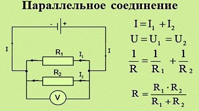
If you take light bulbs of a different power, then other resistors will be needed. It is also imperative to take into account the power for which the resistance is calculated - if the light bulb is 100 watts, then the resistor must be appropriate - either 1 with a capacity of 100 watts, or 2 of 50 watts (but in the second version, the resistors are connected in parallel and their total resistance is calculated by the formula Rtot = (R1 * R2) / (R1 + R2)).
To guarantee, after assembling the control, you can connect it to the network through an ammeter and make sure that a current of the required strength passes through the circuit with a light bulb and a resistor.
RCD testing in a network with grounding
If the wiring is laid according to all the rules - using grounding, then here you can check each outlet separately. To do this, the voltage indicator is to which terminal of the socket the phase is connected, and one of the control probes is inserted into it. The second probe should touch the ground contact and the residual current device should work, since the current from the phase went to ground and did not return through zero.
If suddenly the RCD did not work, then we must remember that this is not necessarily the fault of the device - the ground line may still be faulty.
In this case, additional checks are required and if the grounding test is a separate topic, then the RCD test can be performed directly in the following way.
RCD testing in a single-phase network without grounding
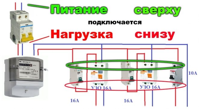
To a properly connected residual current device, the wires from the distribution board come to the upper terminals, and to the protected devices they go from the lower ones.
In order for the device to decide that a leak has occurred, it is necessary to touch the lower terminal with one test probe, from which the phase leaves the RCD, and with the other probe touch the upper zero terminal (to which zero comes from the distribution board). In this case, by analogy with checking with a battery, the current will go through only one winding and the RCD must decide that there is a leak and open the contacts. If this does not happen, then the device is defective.
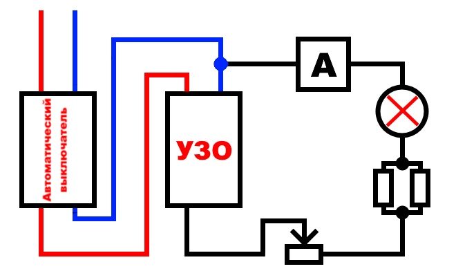
Checking the leakage current at which the RCD is triggered
Here, the same control light with a resistor is used, but in addition to them, an ammeter and one more resistance, a variable, are connected to the circuit. As the latter, a dimmer is often used - a light switch with dimming.
The check procedure is as follows:
- The rheostat (dimmer) is set to maximum resistance and the whole circuit is connected as when checking the residual current device in a network without grounding - one probe to the phase output "from the RCD", and the other to the zero input "to the RCD".
- Further, slowly reducing the resistance of the rheostat, it is necessary to observe the readings of the Ammeter - at what current strength the operation will occur, the RCD is designed for this.
If the setting of the RCD is about 30 mA, there is nothing wrong if the operation occurs at a lower current strength - 10-25 mA - this is a kind of reserve in case of a sharp increase in the leakage current, so that the residual current device has time to be guaranteed to work and the person, even in extreme cases, does not "receive »More than 30 mA.
Clearly about the methods of checking the RCD in the following video:
RCD performance tests - as a result
All the above methods for checking RCDs are rather "rough" tests, because their accuracy is at least influenced by the correctness of the calculations and how "even" the voltage in the network will be. However, they are quite enough for a simple check of the device's performance. The main thing is not to forget to conduct it regularly. Also, it must be remembered that an RCD is a rather complex device - in case of a malfunction, it is better not to try to repair it, but to immediately replace it with a new one.