How to determine the phase and zero in the electrical network with a multimeter?

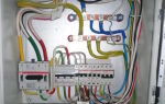
Very often, when performing repair or installation work related to electricity in an apartment, house, garage or in the country, it becomes necessary to find zero and phase. This is necessary for the correct connection of sockets, switches, lighting fixtures. Most people, even if they do not have a special technical education, imagine that there are special indicators for this. We will briefly consider this method, and also tell you about another device that no professional electrician can do without. Let's talk about how to determine the phase and zero with a multimeter.
Content
Zero and phase concepts
Before determining phase zero, it would be good to remember a little bit of physics and figure out what these concepts are and why they are found in an outlet.
All electrical networks (both household and industrial) are divided into two types - with direct and alternating current. From school we remember that current is the movement of electrons in a certain order. With a constant current, electrons move in one direction. With alternating current, this direction is constantly changing.
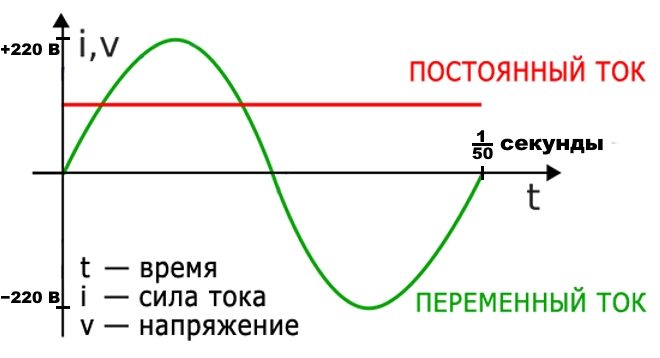
We are more interested in the variable network, which consists of two parts:
- The working phase (usually referred to simply as the "phase"). The operating voltage is applied to it.
- An empty phase, called "zero" in electricity. It is necessary to create a closed network for the connection and operation of electrical devices, and also serves to ground the network.
When we connect devices to a single-phase network, then there is no particular importance where exactly the empty or working phase is. But when we mount electrical wiring in an apartment and connect it to a common house network, you need to know this.
The difference between zero and phase in the video:
The simplest ways
There are several ways to find the phase and zero. Let's consider them briefly.
By color execution of veins
The simplest, but at the same time and the most unreliable way, is to determine the phase and zero by the colors of the insulating sheaths of the conductors. As a rule, the phase conductor is black, brown, gray or white, and zero is made blue or blue. To keep you informed, there are also green or yellow-green conductors, this is how the protective grounding conductors are indicated.
In this case, no devices are needed, they looked at the color of the wire and determined whether this is a phase or zero.

But why is this method the most unreliable? And there is no guarantee that during the installation, the electricians observed the color coding of the cores and did not mix anything up.
Color-coded wires in the following video:
Indicator screwdriver
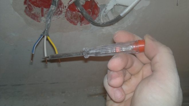
A more truthful method is to use an indicator screwdriver. It consists of a non-conductive housing and a built-in resistor with an indicator, which is an ordinary neon lamp.
For example, when connecting a switch, the main thing is not to confuse zero with a phase, since this switching device works only for a phase gap. Checking with an indicator screwdriver is as follows:
- Disconnect the general input machine for the apartment.
- Use a knife to strip the conductors to be checked from the insulating layer by 1 cm. Separate them between each other at a safe distance to completely eliminate the possibility of contact.
- Apply voltage by turning on the input circuit breaker.
- Use a screwdriver tip to touch the bare conductors. If at the same time the indicator window lights up, then the wire corresponds to the phase one. The absence of a glow indicates that the found wire is zero.
- Mark the required core with a marker or a piece of electrical tape, then turn off the general machine again and connect the switching device.
More complex and accurate checks are done with a multimeter.
Phase search with an indicator screwdriver and a multimeter in the video:
Multimeter. What is this device?
A multimeter (electricians also call it a tester) is a combined instrument for electrical measurements, which combines many functions, the main of which are an ohmmeter, ammeter, voltmeter.
These devices are different:
- analog;
- digital;
- portable lightweight for some basic measurements;
- complex stationary with a lot of possibilities.
Using a multimeter, you can not only determine the ground, zero or phase, but also measure the current, voltage, resistance on the circuit section, check the electrical circuit for continuity.
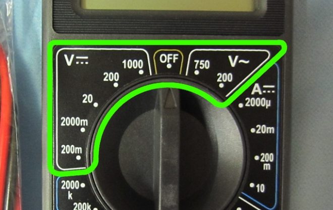
The device is a display (or screen) and a switch that can be set in various positions (there are eight sectors around it). At the very top (in the center) there is a sector "OFF", when the switch is set to this position, it means that the device is turned off. To take voltage measurements, you will need to set a switch in the "ACV" (for alternating voltage) and "DCV" (for direct voltage) sectors.
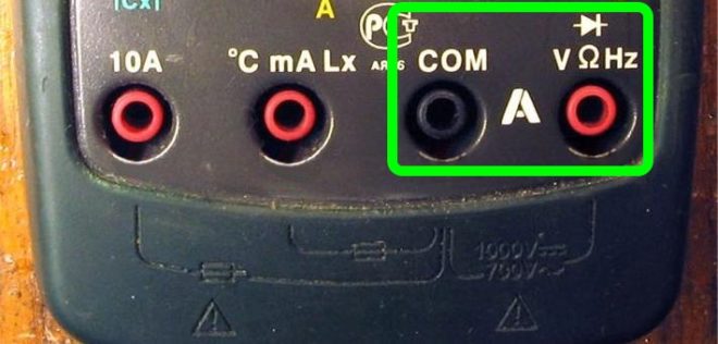
The multimeter kit includes two more test leads - black and red. The black probe is connected to the bottom socket marked "COM", this connection is permanent and is used for any measurements. The red probe, depending on the measurements, is inserted into the middle or upper socket.
How to use the device?
Above, we examined how to find a phase wire using an indicator screwdriver, but it will not work to distinguish between zero and ground with such a tool. Then let's learn how to check the cores with a multimeter.
The preparatory stage looks exactly the same as for working with an indicator screwdriver. With the voltage disconnected, strip the ends of the conductors and be sure to separate them so as not to provoke accidental touching and the occurrence of a short circuit. Apply voltage, now all further work will be with a multimeter:
- Select the measuring range of AC voltage on the instrument above 220 V. Typically, there is a mark with a value of 750 V in the "ACV" mode, set the switch to this position.
- The device has three slots where the test leads are inserted. We find among them the one that is designated by the letter "V" (that is, to measure voltage). Insert the dipstick into it.
- Touch the stripped cores with the probe and look at the screen of the device. If you see a small voltage value (up to 20 V), then you are touching the phase wire. In the case when there is no reading on the screen, you have found zero with a multimeter.
To determine the "ground" clean a small area on any metal element of home communications (it can be water or heating pipes, batteries).
In this case, we will use two sockets "COM" and "V", insert the measuring probes into them. Set the device to the "ACV" mode, to a value of 200 V.
We have three wires, among them we need to find the phase, zero and ground. With one probe, touch the cleaned place on the pipe or battery, with the second touch the conductor. If the display shows a reading of the order of 150-220 V, then you have found a phase wire. For the neutral wire with similar measurements, the reading fluctuates within 5-10 V, when you touch the "ground", nothing will be displayed on the screen.
Mark each core with a marker or electrical tape, and to make sure that the measurements are correct, now take measurements relative to each other.
Touch the two probes to the phase and neutral conductors, a figure should appear on the screen within 220 V. The phase with ground will give a slightly lower reading.And if you touch zero and ground, then the screen will display a value from 1 to 10 V.
A few rules for using a multimeter
Before determining the phase and zero with a multimeter, read a few rules that must be followed when working with the device:
- Never use your multimeter in a humid environment.
- Do not use defective test leads.
- At the time of taking measurements, do not change the measuring limits and do not reposition the switch.
- Do not measure parameters whose value is higher than the upper measuring limit of the device.
How to measure voltage with a multimeter - in the following video:
Pay attention to an important nuance in using a multimeter. The rotary switch must always be set to the maximum position initially to avoid damage to the electronic device. And in the future, if the readings are lower, the switch is moved to low marks to obtain the most accurate measurements.