How to measure voltage in an outlet with a multimeter

Not every day such a skill is useful, but how to check the voltage in the outlet with a multimeter and what it should show at the same time, it is better to find out in advance. In addition to the voltage, the electronic tester is able to measure the current strength and the resistance of the wires, for which the connection of the plugs must be reversed on the device. Their correct connection must be carefully monitored - if measurements are taken incorrectly, a short circuit will occur.
Content
A little theory - how measuring devices are connected
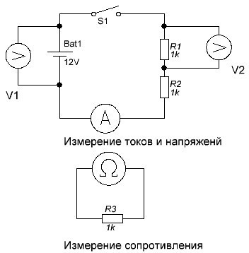 An electronic multimeter combines several different devices that are connected in different ways to a section of the circuit. To use it correctly, you need to know what the voltage is measured and what the current is and how to connect the device correctly.
When the wires are simply connected to a working power source, then an electrical voltage appears on them, which can be measured between plus and minus (phase and zero). This means that the voltage can be measured both with the load connected to the network (the operating device), and without it.
Electric current in the wires appears only when the circuit is closed - only then it begins to flow from one pole to the other. In this case, current measurements are carried out when the measuring device is connected in series. This means that the current must pass through the device and only in this case will it be able to measure its value.
Of course, so that the measuring device does not affect the current strength that it measures, the resistance of the multimeter should be as low as possible. Accordingly, if the device is configured to measure the current strength, and by mistake try to measure the voltage with it, then a short circuit will occur. True, not everything is clear here either - the measurement of current and voltage with modern electronic multimeters is carried out with the same connection of the terminals to the device.
If you recall at least the superficial school knowledge about electrical circuits, then the rules for measuring voltage and current can be formulated as follows: the voltage is the same on the parallel connected sections of the circuit, and the current is when the conductors are connected in series.
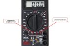
Multimeter scale markings
Different device models have their own characteristics, but their basic capabilities are approximately the same, especially for budget models.
 The simplest instruments can measure:
- ACV - Alternating Voltage. Setting the switch to this division turns the multimeter into a voltage tester, typically up to 750 and 200 volts;
- DCA - DC current. Here you need to be careful - on the scale of many budget devices there are measurement limits of 2000µ (microamperes) and 200m (milliamperes) and the plug must be left in the same terminal as when measuring voltage, and if current strength is measured up to 10 Amperes, then the plug is rearranged to another terminal with the appropriate designation.
- 10A - DC current from 200 milliamperes to 10 amperes. Usually it is drawn on the device that when this mode is turned on, the plug must be rearranged.
- hFe - check transistors.
- > l - checking the integrity of diodes, but most often this function is used as a continuity of wires.
- Ω - measurement of the resistance of wires and resistors. Sensitivity from 200 Ohm to 2000 kilo-ohms.
- DCV - constant voltage.The sensitivity is set from 200 millivolts to 1000 volts.
There are usually two wires connected to the multimeter connectors - black and red. The plugs on them are the same, and the colors are different solely for the convenience of the user.
Wire resistance measurement
This is the simplest mode of operation - in fact, you need to take the wire for which you need to measure the resistance and touch the multimeter probes to its ends.
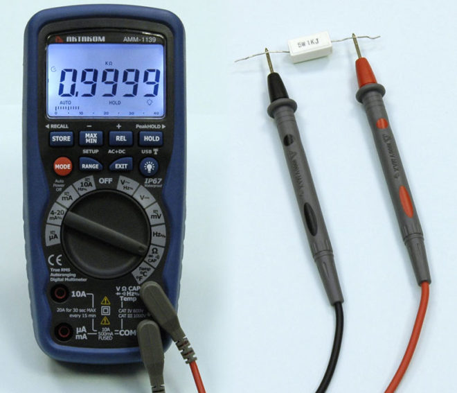
Resistance is measured thanks to the power source inside the multimeter - the device measures its voltage and current in the circuit, and then calculates the resistance according to Ohm's law.
There are two nuances when measuring resistance:
- The multimeter shows the sum of the resistances of the measured wire together with the probes that touch it. If exact values are needed, then the wires of the probes should be measured initially and then the result obtained should be subtracted from the total.
- It is difficult to estimate in advance the approximate resistance of the wire, so it is advisable to make measurements by lowering the sensitivity of the device.
Voltage measurement
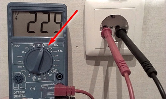
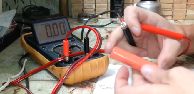
Usually, in this case, the task is how to measure the voltage in the outlet or just check its presence. The first things to do is prepare the tester itself - the black wire is inserted into the terminal marked COM - this is a minus or "ground". Red is inserted into the terminal, which has the letter "V" in the designation: it is often written next to other symbols and looks something like this ֪– VΩmA. Boundary values - 750 and 200 Volts are shown near the mode dial of the multimeter (In the section labeled ACV). When measuring the voltage in the outlet, the voltage should be about 220 volts, so the switch is set to division 750.
Zeros will appear on the device screen - the device is ready for operation. Now you need to insert the probes into the outlet and find out what voltage is in it now and if there is any at all. Since it is necessary to measure the voltage in the AC network, there is no difference with which probe to touch the phase, and which zero - the result on the screen will be unchanged - 220 (+/-) Volts if there is voltage in the socket or zero if it is not there. In the second case, you need to be careful - if there is no zero in the outlet, then the device will simply show that the outlet is inoperative, so in order not to get an electric shock, it will not hurt to check the contacts with a voltage probe.
In the same way, DC voltage is measured - with the only difference that the probe with the black wire must touch the minus, and the red one - plus (if they are correctly connected to the terminals of the device). The mode dial, of course, must be moved to the DCV area.
There is the same nice feature here as when measuring alternating voltage: in fact, when determining the voltage, you can touch both the minus and plus points with a black probe - just if you mix up the polarity, the correct result will be displayed on the device screen, but with a minus sign.
These are all the features that you need to know before measuring the voltage with a multimeter - in any device or outlet.
Current measurement
It is good if the farm has a relatively good multimeter with an A ~ mark on it, which shows the ability of the device to measure AC current. If budget devices are used for measurement, then, most likely, there will only be a DCA (direct current) mark on its scale, and in order to use it, additional manipulations will need to be performed, for which you will have to remember the basics of building electrical circuits.
If the device "knows how" to measure the alternating current "out of the box", then in general everything is done in the same way as for measuring voltage, but the multimeter is connected to the circuit in series with the load, for example, an incandescent lamp. Those.from the first socket of the socket the wire goes to the first probe of the multimeter - from the second probe the wire goes to the first contact on the lamp base - from the second contact of the base the wire goes to the second socket of the socket. When the circuit is closed, the multimeter will display the current flowing through the lamp.
Read more about measuring current strength in this video:
Measuring AC current with a voltmeter
If you need to measure the AC current, but you only have a budget multimeter at hand, which does not have such functionality, then you can get out of the situation using the measurement method using shunting. Its meaning is displayed by the formula I = U / R, Where I is the current strength to be found, U is the voltage on the local section of the conductor, and R is the resistance of this section. It is clear from the formula that if R is equal to unity, then the current in the circuit section will be equal to the voltage.
To measure, you need to find a conductor with a resistance of 1 Ohm - this can be a rather long wire from a transformer or a piece of a spiral from an electric stove. Wire resistance, i.e. its length are regulated by the tester in the appropriate test mode.
As a result, you get the following scheme (incandescent lamp as a load):
- From the first socket of the socket, the wire goes to the beginning of the shunt, one of the multimeter probes is also connected here.
- The second probe of the multimeter is connected to the end of the shunt and from this point the wire goes to the first contact of the lamp base.
- From the second contact of the lamp base, the wire goes to the second socket of the socket.
The multimeter is set to AC VOLTAGE MEASUREMENT MODE. In relation to the shunt, it is connected in parallel, so that all the rules are followed. When the power is turned on, it will indicate a voltage equal to the current flowing through the shunt, which in turn is the same as across the load.
Visually about this measurement method in the video:
As a result
Even a budgetary universal measuring device - a multimeter allows measurements to be made within a fairly wide range, sufficient for home use. But when buying a device, you need to at least in general terms imagine for what purposes it will be used - it may be more correct to overpay a little, but as a result, have a tester “on hand” capable of performing any task assigned to it. Also, before using it, it will not hurt, at least in general terms, to refresh in memory the basics of building electrical circuits and using electrical measuring instruments in them.