Connection diagram of the pass-through switch from 3 places

Before, everything was simpler, we lived in standard houses with a standard electric lighting network. We went into the room, pressed the switch, the light came on, and when we left, they turned off. Now more and more often in city apartments and country houses the interior is designed by designers, and they may have such a vision of your future home that the issue of controlling the same lamps from several places will become very relevant. In this case, a pass-through switch will come to the rescue. A 3-point connection diagram is considered not too complicated and at the same time as comfortable as possible. Let's talk about it in more detail, when and where it is used, how to connect everything yourself and what is required for this?
Content
Where to apply such a scheme?
Pass-through switches were invented so that the same lighting devices (or groups of them), located in long corridors or large rooms, could be supplied and removed from different points.
The connection diagram of the pass-through switch from exactly three places is most often used under the following circumstances:
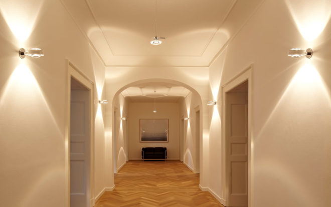
- When there are long corridors, from where there are exits to several different rooms or premises. At the entrance to such a corridor, the lighting is turned on by one switch, and then somewhere in the middle there is a second, and at the end of the room a third switching device. With their help, you can turn off the lighting from the point where you are at the moment, and not return for this to the beginning of the corridor.
- In country houses for lighting a personal plot or yard. For example, when leaving the house, one switch is installed, which turns on the lamps in the yard. And the other two are installed on some yard buildings (garage, shed), reaching which you can turn off the lighting.
- In apartment buildings with three floors. At the entrance to the first floor, they turned on the light in the entire entrance, went up to the second or third floor, turned off. In this case, the connection diagram of the pass-through switches allows you to significantly save electricity, because it often happens that the light in the entrances is on day and night.
- When a large children's room has several sleeping places. A total of three switches are installed: one at the entrance to the room, two others near the cots. Entering the bedroom, the child turns on the light, reaches his bed, lies down in bed and turns off the lighting.
- In country houses, using a pass-through switch from three places, you can control the lighting of staircases or flights. One device is installed at the bottom at the beginning of the stairs, when it rises, it turns on the lighting of the entire march. Having risen to the second floor, another switch is installed, with which the light is turned off. And the third is located higher, where the stairs go to the attic, so that after going up there you turn off the lighting of the entire march and not wind up extra kilowatts while you go about your business in the attic.

In fact, there are still a lot of options, we have considered the most popular ones, but even from this it is clear how much the connection diagram of the pass-through switch from 3 places will make our life more comfortable.
Switching diagram
What is special?
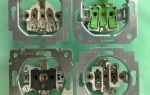
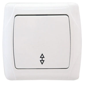
Externally, a pass-through switching device looks like an ordinary one, but this is not yet you begin to carefully study its device.
Have conventional apparatus there are two contacts - input and output, when you press the key, they close or open among themselves, thus creating an electrical circuit or breaking it.
 Have pass-through switch three contacts - one common input and two output. Inside the contact part, there is a cross member which is never in an intermediate position in the middle. When you press the key, it switches to one or the second circuit, thus it connects the common input contact with one or the other output.
The triple lighting control option uses a cross switch. Its design feature is that there are four contact points (two input and two output).
The cross switch connection is always made in the middle between the bushings. One pair of its contacts is connected to the outgoing contacts of the first pass-through device, the second pair, respectively, to the outgoing contacts of another pass-through switch.
Keep in mind that when connecting switches from 3 different locations per lighting group, all three switching devices duplicate each other's actions. In this regard, their keys will not have clearly marked positions "on", "off", each time they can be in different positions.
The principle of operation of the pass-through and cross-over switches is shown in detail and accessible in the video from Alexei Zemskov:
What is required?
For the production of electrical work, purchase the following materials:
- junction box;
- lighting device;
- pass-through switches - 2 pcs .;
- cross switch;
- socket boxes - 3 pcs.;
- 2-wire, 3-wire and 4-wire.

Also, when working, you should always have such instruments:
- side cutters;
- screwdriwer set;
- a tool for removing the insulating layer from wire cores;
- multimeter;
- tool for making strobes and holes in the walls.
Electrical switching
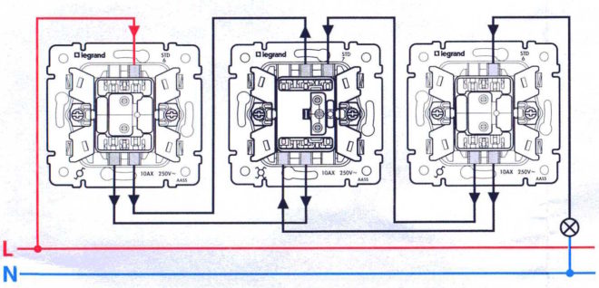
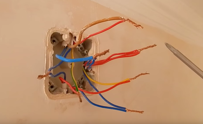
The junction box must fit five wires:
- 2-core - zero and phase from the supply network;
- 2-core - zero and phase from the lighting device;
- 3-core - from one pass-through switch;
- 3-core - from the second pass-through switch;
- 4-wire - from a cross switch.
If your luminaire is structurally to be grounded, then you will need a wire with three cores both for connecting the lighting device and for the power supply (phase, ground and zero).
Each connection must be made in a junction box, it is convenient - in one place to switch several sections of electrical wiring at once. The box itself acts as an intermediate link between the supply network and the feed-through switches.
Now let's connect, there is nothing difficult, the main thing is, be careful:
- First, the neutral wire from the supply network is connected to the neutral core wire going to the luminaire.
- Connect the phase wire from the mains to the core going to the common input contact of the first pass-through switch.
- Now a pair of wires from the outgoing contacts of the first pass-through switch is connected to any one pair of wires of the crossover device.
- Absolutely similar switching is performed with the second pass-through switch. Its pair of wires from the outgoing contacts is connected to the remaining pair of wires of the crossover apparatus.
- It remains to connect the phase of the lamp to the core of the common incoming contact on the second pass-through switch.
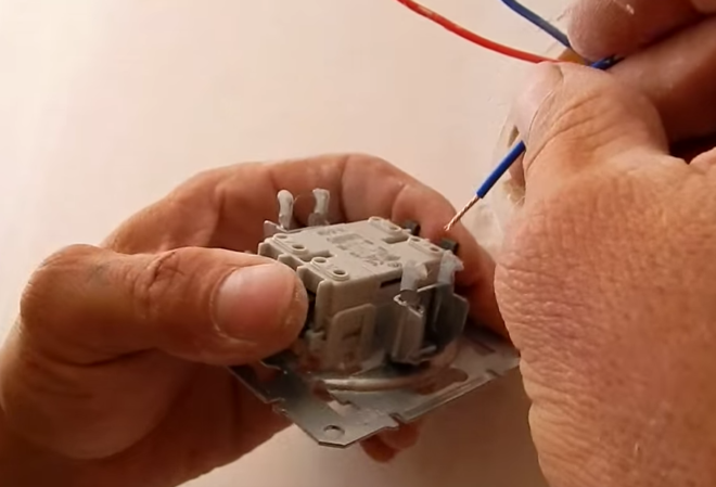
Make the appropriate conductor connections at the contacts of the switches and in the lamp holder (phase and zero).
We advise you to first test the work of the assembled circuit, and then only isolate the twist points in order to see exactly that everything is done correctly. Turn on the machine from the power source, and test the action of the switches. By any of the three switching devices, the lamp turns on and off.Is everything working correctly? Then finish the work. Disconnect the voltage again, insulate the twist points with electrical tape, fasten the protective covers and buttons to the switches.
The connection diagram is carried out in a similar way two-key pass-through switch, only in this situation you need to install two crossover devices.
You can connect both the fourth switch and the fifth to the lighting control circuit, then it will be possible to control even more space, for example, the driveway lighting of a multi-storey building. Of course, in such cases, the scheme will be more complicated. But if you understand the principle itself on the considered control scheme of three places, you will also be able to cope with a large number of points.
Video compilation
This video shows the operation of two pass-through and toggle switches on a specially assembled stand:
Another detailed description of the same circuit, only the switches are connected directly:
And a practical example is installing three switches in a long hallway: