Pass-through switch - connection diagram for two points

If you are interested in such a question as the connection diagram of the pass-through switch, then most likely you already know what kind of device it is and how it works. For those who first encounter such a concept, we will briefly tell you what pass-through switches are for and what is their difference from ordinary devices, and then we will consider in detail how to connect the pass-through switch yourself. If you are at least a little bit friends with electricity and in life you have ever installed sockets with switches yourself, then there should be no problems with the through device. The main thing is to carefully understand everything.
Content
Where are they used?
Pass-through switches are switching devices with which you can control one lighting fixture from two places, due to which they have a fairly wide range of applications.
This lighting control is very convenient in large areas, such as concert and sports halls, or long corridors and tunnels. Two switches are installed at different ends of the room and from both of these points, you can turn on and off the lamps. That is, they entered the corridor, pressed the switch key at the entrance and the lights in the room lit up, then they walked through the whole room, and at the exit, the second switch turns off the lighting devices.

Particularly convenient and practical is the wiring diagram for a pass-through switch from 2 places in large country houses, where there are large living rooms and dining rooms, staircases and marches, lighting of the yard and garden paths. For example, through such a switch, you can connect an external lantern that illuminates the entrance to the house. You turned on the lamp from the street, and when you entered the house, you turned it off from the inside. And, conversely, when leaving the house on the street, you turned on the street lamp from the room in advance, and then turned it off on the street.
The use of such switching devices, in addition to practicality, also brings an economic effect, due to the fact that electricity consumption is reduced. For example, going up the stairs, on the first floor, you turn on the lighting with one switch, and on the second, turn off the other. If the light switch at the entrance to the stairs is an ordinary one, then until you go back down, the lamp will be on, and the meter will wind up kilowatts.

In ordinary apartments, connecting a pass-through switch is relevant in bedrooms, when you turn on the lighting at the entrance to the room, turn it off while lying in bed using a second device installed somewhere near the head of the bed.
It is especially convenient to use such switches in residential premises where there are walk-through rooms.
So if you plan to repair or install new electrical wiring in the house, be sure to pay attention to the possibility of using a pass-through switch. The lighting control scheme will really make your life much more comfortable.
Design features
 Before considering possible options for connecting pass-through switches, it is necessary to thoroughly understand its design and principle of operation, then everything will become clear and the scheme for connecting it to the general electrical network does not seem so complicated.
Outwardly, such a device is no different from an ordinary switch. However, they perform completely different functions. A conventional apparatus has two states:
- "On", in this case, the electrical circuit is closed, through which current flows and voltage is supplied to the lighting device, as a result of which the lamps light up;
- "Off", the electrical circuit is open, the current only reaches the point where the circuit is broken, no voltage is supplied to the lamp, and the lamps do not light up accordingly.
Even if you put two conventional switches on one light bulb at different ends of the room, you just get a chain of serial connection of elements, you will not be able to control the lighting from 2 places.
The main difference between a pass-through switch and a conventional one is in the contact system.
An ordinary device has two places for connecting wires, that is, one contact at the input and one at the output. And inside the contact system there is a movable element, which, when exposed to it using a drive with a key, closes or opens the input and output contacts.
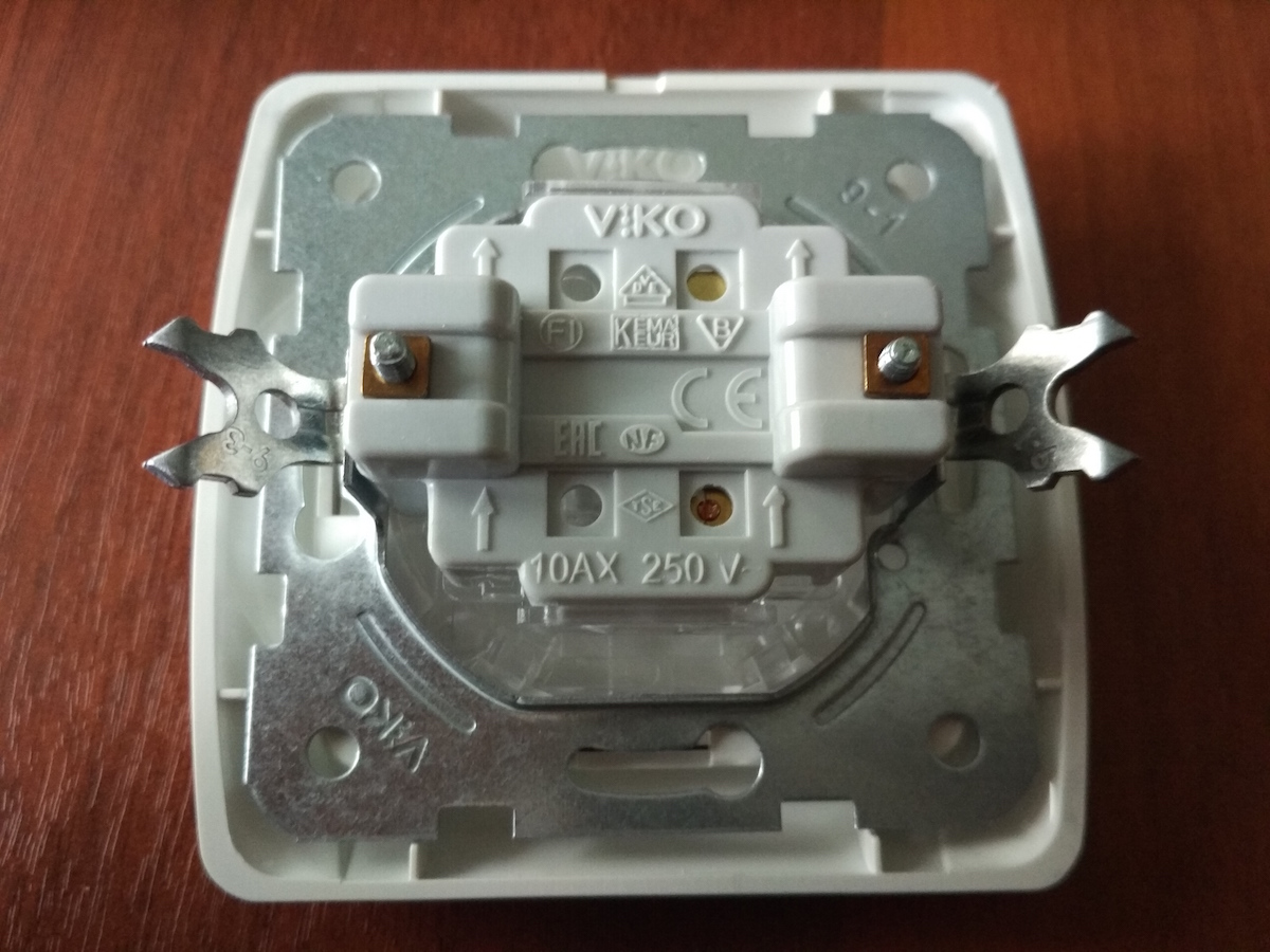
The through-switch design has three contacts - one at the input and two at the output. When you press the key and with its help act on the internal movable element (in this device it is of the flip type), it will in any case close one or the second chain, it cannot stand in the middle. That is, there is always a chain between the input and one of the outputs, the internal movable element, as it were, is thrown to one output or to another.
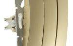
This is how the contact system of the pass-through switch looks and works. Well, on top, like a regular device, it has a plastic protective frame and a key with which you switch. The only difference is that there are small triangles on the key, as if arrows directed in different directions, it is by this marking that you can distinguish a pass-through switching device from a conventional one.
Switching diagram, installation and connection
Required materials and tools
To implement a control scheme for one lamp from two different places, you need the following elements:
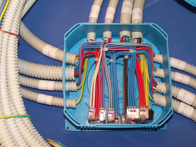
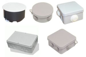 A junction box (many call it a junction box in another way). It is a round or rectangular container made of plastic and has holes on the sides, into which the wires of the electrical network are inserted. Such a box has a lid, which in no case can be hidden under a layer of plaster or wallpaper, it must remain accessible, in case you have to perform some switching actions in the box. In fact, such a box is an intermediate link in the electrical wiring of the apartment between the switchboard and the switches. Its main purpose is to perform wire disconnection, which is very convenient when several sections of electrical wiring are switched in one place.
 Socket boxes. They are needed to securely fix the switches in the wall holes. Previously, they were made of metal, but now such socket boxes are losing their relevance, now they are increasingly made of non-combustible plastic. They come in round and square shapes. Also, when buying, consider what your walls are made of - socket boxes are produced for concrete and plasterboard surfaces.
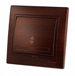
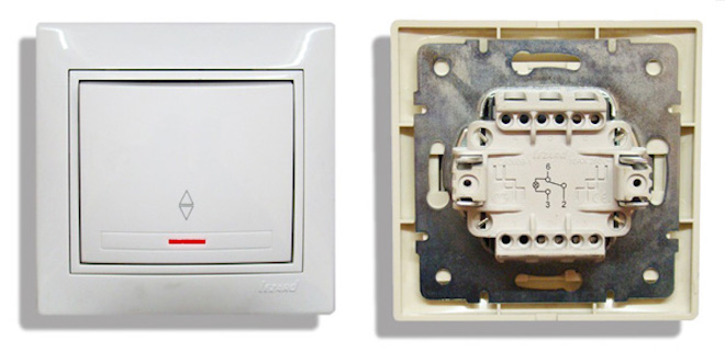
 Pass-through switches. When buying, select a model for the general interior of your room (now it is not a problem to do this, on the market of electrical goods you can really find options for any color)What else I would like to advise is to purchase a model of a pass-through switch with illumination. It is very convenient to quickly find the location of the device in a dark room (there is a special window in the key of this model, through which the highlighting occurs). Try to purchase products from well-established companies (Lezard, Legrand, Viko). They will definitely have a diagram on the back of the contact part, while a switch made in China may not have a diagram.
 Lamp. We do not give you any recommendations here, choose the lighting device according to your taste and color. Any lamps can be connected through such a pass-through device - incandescent, fluorescent, halogen.
Of tools for work you will need a multimeter (or tester), screwdrivers (Phillips and flat), an indicator screwdriver, pliers or side cutters, a knife or other tool for stripping insulation from wires, a level and a tape measure, as well as a puncher with special attachments in order to make holes in the wall for mounting boxes.
Preparing the strobe
Before making grooves, I would like to warn right away, do not run to the hammer and chisel, or to the power tool. The first thing you need is a pencil and paper.
First, depict on a piece of paper the entire plan of your wiring: where the lamps and the junction box will be located, where it is better to install the first pass-through switch, and where the second is, how best to bring electrical wires to all these elements. Be sure to consider what your walls are made of, which method to choose for chasing. The laying of wires in the walls is not done thoughtlessly, there are regulatory documents that should not be neglected, but it is better to take and read.
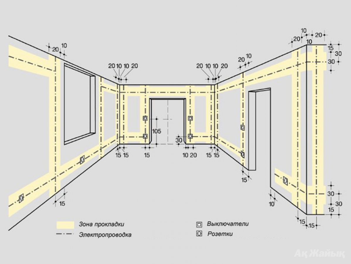
I would like to recall the most basic points:
- The strobes are made only vertically or horizontally, there should not be any inclined.
- Do not bring vertical grooves closer to door and window openings to a distance of less than 100 mm, and to gas pipes - less than 400 mm.
- The path of the groove from the junction box to the installation locations of the switches should have a minimum number of turns.

According to the rules, plan the electrical wiring, outline the paths for the wires along the walls, and only then proceed to the strobing. To do this, you can use:
- A chisel with a hammer (as they say, cheap and cheerful, but for a long time, not very convenient and not very even, the strobes are obtained).
- Grinder (convenient and fast, the strobes are even, but there is a lot of dust at the same time).
- A hammer drill or hammer drill (quick and clean, but the strokes are not very straight).
- A special tool chaser (the grooves will be ideal, with the width and depth of the given dimensions, but the tool itself is too expensive).
Video tutorial on wall chipping:
Clean the finished strobes of dust with a broom or vacuum cleaner. Now you can lay wires in them and fix them with alabaster.
In the case of walls made of plasterboard sheets, the wires are laid in mounting boxes, trays, corrugated pipes.
Holes for the junction box, as a rule, are made under the ceiling at a distance of 10-15 cm from it. Make mounting boxes for switches as you like, but usually they are placed at the level of an adult's lowered hand.
Electrical linkage
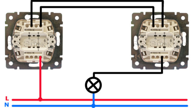
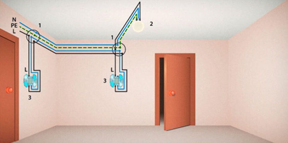
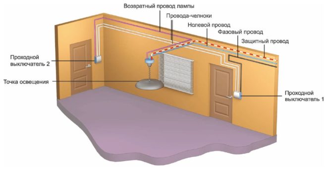
The wiring diagram for a simple pass-through switch is as follows. You will have 4 three-core wires laid to the junction box:
- one from the switchboard (phase, zero and ground come from the supply network);
- one wire per lighting fixture (also phase, zero and ground). If your luminaire is not structurally grounded, then a two-wire wire (only phase and zero) will be enough for you.
- separate three-core wires must be laid on 2 pass-through switches from the junction box.
The wire cross-section should be selected depending on the power of the connected lighting load.
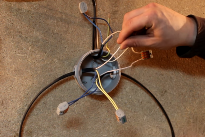
In the junction box, you have 6 connections:
- The zero coming from the supply network must be connected to the zero core going to the lamp holder.
- The grounding conductor from the supply network is respectively connected to the grounding of the luminaire.
- The phase from the mains is connected to a wire that is connected to the incoming contact of the first pass-through switch.
- The phase of the lighting fixture is connected to a wire that is connected to the input contact of the second pass-through switch.
- There are two wires left from the outgoing contacts of the first switch and two wires from the outgoing contacts of the second. They must be connected in pairs in a junction box. There will be two more connections.
Connection order
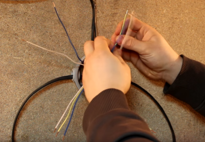
Start connecting wires in the junction box with the neutral wire. It is very convenient when each core has a separate color design. As a rule, a core in blue insulation is taken as zero. Take and connect the blue cores of the wire coming from the mains and going from the junction box to the lamp.
Then connect the grounding wires from the mains and from the luminaire, this can be a core, the insulation of which is made in yellow or green.
Next, connect the phase wires. As a rule, a conductor in white insulation is taken as a phase. Connect the white conductors of the wires from the mains and the first pass-through switch. Do the same with the white conductors of the lamp wires and the second pass-through switch.
Now you have two pairs of unconnected wires left in the junction box - blue and yellow (green), coming from the output contacts of the two switches. Everything is very simple here - connect them together by color.
Make the necessary connections in the lamp holder, connect the phase and neutral conductors to its contacts, and also ground the lamp body.
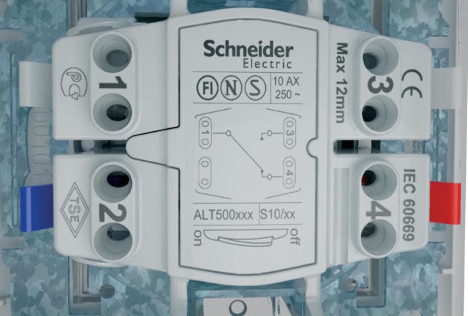
Now you need to connect the wires to the terminals of the switch. Take the device in your hands and take a close look at its back side, all terminals are marked. On the side where there is one terminal and the letter "L" is drawn, connect the phase white wire. Connect the same core colors to the terminals marked with numbers "1" and "2", respectively, in the first and second switches (for example, blue to "1", yellow (green) to "2").
Fasten the switches in the socket boxes, install the protective covers and keys.
Before insulating everything in the junction box, it is advisable to check the correct operation of the pass-through switches. Apply voltage from the switchboard, press the key of the first switch, the lamp should light up. Now press the button of the second switch, the lamp has gone out. Do this several times and in reverse order. If everything is working well, then the connected luminaire is correctly connected to the control circuit from two different places.
In detail, the connection diagram of the pass-through switch is understood in these videos:
Completion of work
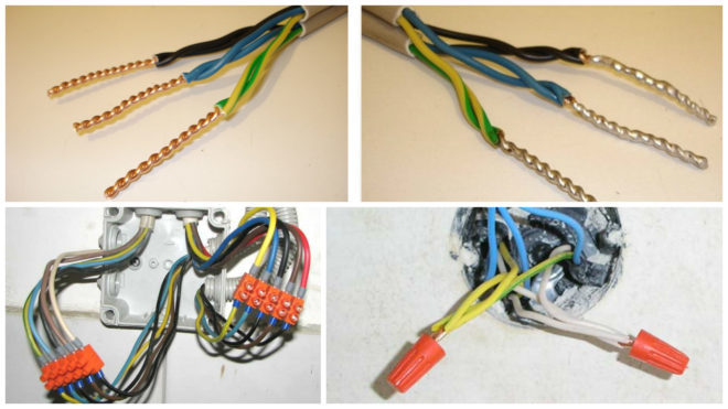
And now quite a bit about how to properly insulate the connections in the junction box.
First, it is desirable to solder the twists for reliability.
Second, insulate only with materials specifically designed for this. PVC insulation tape is best suited. Moreover, now it is available in various colors, you can wrap each connection with the corresponding color with electrical tape, thus denoting zero, phase and ground.A good modern and reliable insulating material is heat shrink tubing. Also, the places where the wires are twisted can be insulated with PPE caps.
Sometimes there are situations when one group of lighting fixtures needs to be controlled not from two, but from three places. For example, in a multi-storey building, when it is desirable that the lighting can be turned on and off on each floor. Or in very long corridors with doors from several rooms (offices, hotels, hotels). In this case, the three-point circuit breaker connection diagram, this will be discussed in detail in a separate article.
Some people prefer to install luminaires with motion sensorsrather than a pass-through switch. Their connection diagram is also not complicated, but in terms of practicality, motion sensors still lose to pass-through switching devices. There are too many factors that will influence the constant on / off of these sensors (the number and time of stops, the speed of movement, etc.).
As you can see, there is nothing difficult in connecting pass-through switches. So if in your apartment or country house there are places for applying such a scheme, do not neglect it. Starting to use, you will soon feel how convenient and comfortable it is.