How to measure resistance with a multimeter - basic rules and procedure

There are many situations when it will be useful to know how to measure resistance with a multimeter and is there a difference in which device it is best to do it. Even if a person is not an avid radio amateur, then when doing household work with an electrician, it is often necessary to at least "ring" the wires - in fact, to make sure that the resistance of the wire is within acceptable limits.
Content
- How a multimeter measures resistance
- Which multimeter to use
- Turning the multimeter into ohmmeter mode and selecting the measurement limits
- Continuity of wires - checking the integrity of the electrical circuit section
- Conducting resistance measurements and what nuances may arise
- How to measure resistance with a multimeter - summary
How a multimeter measures resistance
The principle of resistance measurement is based on Ohm's law, which in a simplified version says that the resistance of a conductor is equal to the ratio of the voltage on this wire to the current that flows through it. The formula looks like R (resistance) = U (voltage) / I (current). That is, 1 Ohm of resistance indicates that a current of 1 Ampere and a voltage of 1 Volt flows through the wire.
Accordingly, by passing a predetermined current with a known voltage through a conductor, its resistance can be calculated. In fact, an ohmmeter (a device that measures resistance) is a current source and an ammeter, the scale of which is graduated in ohms.
Which multimeter to use
Measuring devices are divided into universal (multimeters) and specialized, which are designed to perform one operation, but carry it out as quickly and accurately as possible. In a multimeter, an ohmmeter is only a component part of the device and it still needs to be turned on in the appropriate mode. Specialized devices, in turn, also require some skills to use - you need to know how to connect them correctly and interpret the received data.
How to use analog and digital multimeters - in the following video:
Specialized measuring instruments
It is clear from Ohm's law that a standard multimeter will not be able to measure large resistances, since standard finger-type ones are used as a power source, or a "Krone" -type battery - the device simply does not have enough power.
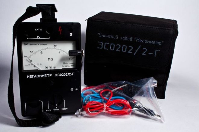
If it is often necessary to measure a large resistance, for example, insulation, then you need to purchase a megohmmeter.
It uses a dynamo or a powerful battery with a step-up transformer as a current source - depending on the class of the device, it can generate voltages from 300 to 3000 volts.
From this it follows that the task, for example, how to measure the grounding resistance with a multimeter, cannot have an unambiguous answer - in this case, you need to use a specialized device designed specifically for this purpose. Measurements are carried out according to certain rules and the use of such devices is the lot of specialists - without specialized knowledge, getting the correct result is quite problematic. Theoretically, you can check the resistance at grounding with a tester, but this will require the assembly of an additional electrical circuit, which will require at least a powerful transformer, like the one used on welding machines.
Digital and analog multimeters
Outwardly, these devices are easy to distinguish from each other - in digital, the data is displayed in numbers, and in the analog dial, it is graduated and the arrow points to the desired value.Accordingly, a digital device is easier to use, since it immediately shows the ready-made value, and when working with an analog device, you will have to additionally interpret the output data.
Additionally, when working with such devices, it must be borne in mind that the digital multimeter has a power supply discharge sensor - if the battery current is not enough, then it will simply refuse to work.
Analogue, in such a situation, will not say anything, but will simply give incorrect results.
Otherwise, for domestic purposes, any multimeter is suitable, on the scale of which a sufficient resistance measurement limit is indicated.
Turning the multimeter into ohmmeter mode and selecting the measurement limits
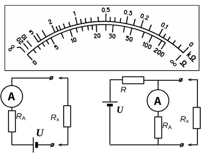
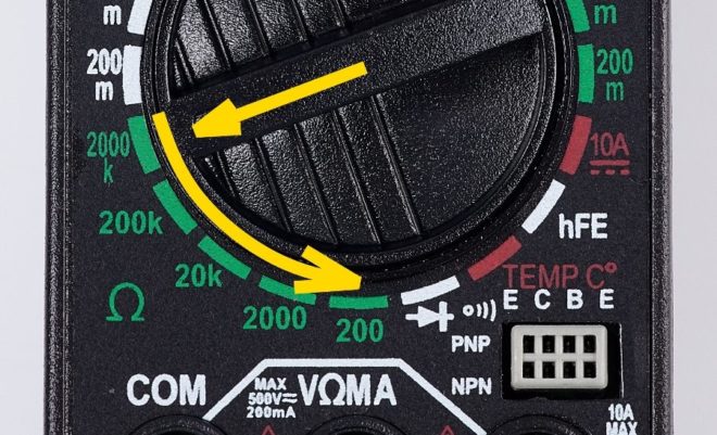
The multimeter is controlled with a round rotary knob, around which a scale is drawn, divided into sectors. They are separated from each other by lines or simply the inscriptions on them differ in color. To turn the multimeter into ohmmeter mode, you need to turn the knob to the area of the sector indicated by the "Ω" (omega) icon. The numbers that will indicate the operating modes can be signed in three ways:
- Ω, kΩ - x1, x10, x100, MΩ. Usually, such designations are used on analog devices, in which what the arrow shows still needs to be translated into the usual values. If the scale is graduated, for example, from 1 to 10, then when each mode is turned on, the displayed result must be multiplied by the specified coefficient.

- 200, 2000, 20k, 200k, 2000k. Such a record is used on electronic multimeters and shows in what range the resistance can be measured when the switch is set to a certain position. The prefix "k" denotes the prefix "kilo", which in the unified measurement system corresponds to the number 1000. If you set the multimeter to 200k and it shows the number 186, this means that the resistance is 186000 Ohm.
- Ω - If there is only such an icon on the ohmmeter case, then the multimeter is able to automatically determine the range. The dial of such a device can usually display not only numbers, but also letters, for example, 15 kΩ or 2 MΩ.
The first two methods of labeling the scale have a direct relationship between the accuracy of displaying the results and their error. If you immediately turn on the maximum range, then the resistance of the order of 100-200 ohms will most likely be shown incorrectly.
The test leads of the device must be inserted into the corresponding sockets - black in "COM", and red in the one near which, among other designations, there is an "Ω" icon.
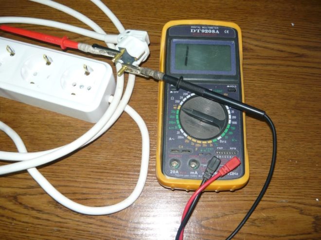
Continuity of wires - checking the integrity of the electrical circuit section
There are two ways to call the wires with a multimeter, the use of which depends on the presence of a sound signal in the device. This function, if any, on different devices can be turned on by different switch positions - therefore, you need to pay attention to the icons that are painted on the device case.
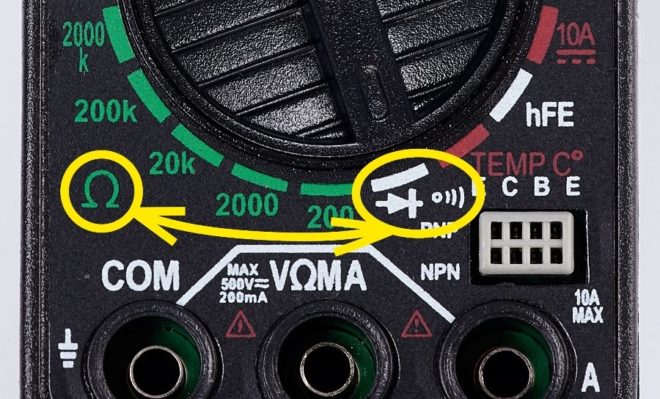
The buzzer is shown as a point, to the right of which three semicircles are drawn, each larger than the previous one. You need to look for such an icon either separately, or above the smallest number of the resistances, or near the diode icon, which is displayed as an arrow on a line, with its sharp end abutting another line perpendicular to the first line.
If you turn on the tester in the dialing mode, it will beep if the resistance of the measured conductor is less than 50 Ohm. In some devices, this can be 100 ohms, so if accuracy is needed, then you need to check the device's passport.
Clearly about the continuity of the wires in the video:
The dialing procedure is simple and intuitive - set the switch opposite the buzzer icon and touch the ends of the conductor that you want to "ring" with the probes:
- If the wire is intact, the multimeter will beep.
- If the wire is intact, but due to its length the resistance is greater than that at which the buzzer sounds, then the display will show a figure showing its value.
- If the resistance is significantly greater than the range for which this operating mode is designed, then the display will show a unit - it means that you need to move the switch to another mode and repeat the measurement.
- If the integrity of the wire is broken, then no indication will occur.
If an analog multimeter is used to "ring" the conductors without a sound signal, then it is set to the minimum measurement range - if, when the probes touch the wire, the arrow shows a value tending to zero, then the wire is intact. The same goes for digital instruments without a buzzer.
Before checking the resistance of the conductors, you must first always perform a test of the device itself - touch the probes to each other. You also need to check how the device reacts to the human body - some people have a fairly low resistance and if you press the ends of the wire to the probes with your hands, the device can show that the conductor is intact, even if it is not.
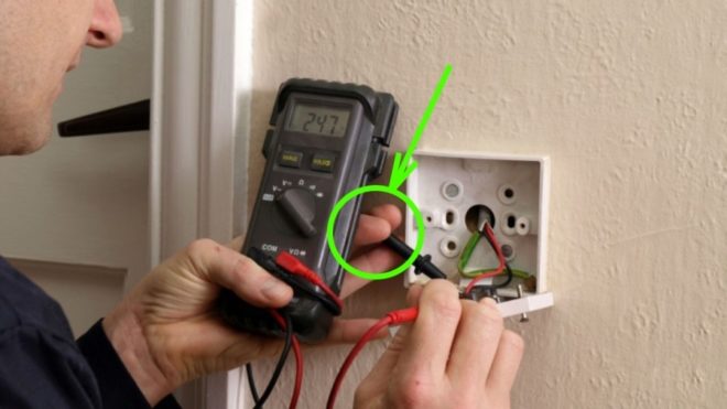
Conducting resistance measurements and what nuances may arise
The multimeter probes are connected to the same sockets and in general, the resistance measurement is performed in almost the same way as the continuity of the wires, but since it is not only necessary to check the integrity of the conductor, this process has some peculiarities.
- Selection of measurement boundaries. When the measured resistance is at least approximately known, the regulator sets the nearest higher value (if the multimeter does not automatically detect it). If the resistance is not known exactly, then it is worth starting measurements from the largest value, gradually switching the multimeter to a smaller one.
- When accuracy is needed, it is imperative to take into account errors. For example, if there is a resistance of 1 kOhm (1000 Ohm) on the resistor, then firstly, you must take into account the tolerances for its manufacture, which are 10%. As a result, real numbers can be in the range from 900 to 1100 ohms. Secondly, if you take the same resistor and set the multimeter to the maximum value, for example 2000 kOhm, then the device can show one, i.e. 1000 Ohm. If after that you move the switch to the 2 kΩ position, then most likely the device will show another - more accurate figure, for example, 0.97 or 1.04.
- If you need to check the resistance of a part that is soldered into the board, then at least one of its terminals must be soldered. Otherwise, the device will show an incorrect result, since with a high degree of probability there are other conductors in the diagram in parallel to the tested part.
If an element with several leads is being checked, then this part must be completely soldered from the circuit.
- The human body conducts current and has a certain electrical resistance. Therefore, as in the case of parts soldered into the board, it is necessary to exclude the possibility of their contact with foreign objects - in this case, these are the hands of the person measuring. In an extreme case, you can press the contact to the probe with the fingers of one hand, but touching the other with the other is categorically unacceptable - the measurement result in this case will be deliberately incorrect.
- In some cases, it is necessary to take into account the contact resistance - even clean solder or the legs of unused radio components can become covered with an oxide film over time, so it is advisable to clean or scratch the contact point at least minimally with the end of the probe.
How to check the resistance of the wire is clearly shown in the video:
How to measure resistance with a multimeter - summary
The control of modern digital multimeters, and most of the analog ones, is made as convenient as possible for the operator and does not require deep knowledge. It is intuitively understandable even to a non-professional without specialized education - often to master and use the device correctly, it is enough to recall school physics lessons on building and checking electrical circuits.It is advisable to remember the above nuances when making measurements, because they will in any case "come out" in the process of using the multimeter.


