Is it possible to measure the grounding resistance with a multimeter and how to do it correctly?

The fact that the rules are required to periodically measure the grounding resistance is not just someone's invention or whim, it is, first of all, a matter of the safety of human life. There are certain standards and measurements must comply with them. In this article, we will look at how to measure ground resistance with a multimeter and other measuring instruments.
Before you check the grounding in a private house, it is very important that you understand the very essence of this procedure, why it is performed, what is the main goal, why is it so necessary?
Content
What is grounding?
Protective grounding is the deliberate connection to the ground of those parts of electrical equipment that, during normal operation of the electrical network, are not under the influence of voltage, but can be affected by it as a result of insulation breakdown. The main purpose of grounding is to protect people from electric current.
The main component of protective grounding is the loop. It is a design of natural or artificial ground electrodes, that is, several grounding electrodes are connected into a single whole. Steel rods are most often used as electrodes. Copper rods are used less often due to the fact that it is expensive.

But if you can afford it, keep in mind that copper is the ideal option and the best conductor.
Logically, it is clear that the ground loop should be located in the ground. Since we are interested in protecting the house, a suitable place with normal soil is chosen not far from the building and the power shield. Three pins are driven into the ground so that they are located in a triangle, and the distance between them is 1.5 m.
These electrodes must be driven in as deep as possible (their length must be at least 2 m).
Now you need a welding machine and a metal bus, with which the electrodes need to be tied together in an equilateral triangle. The circuit is ready, now you need to fix a copper conductor to it, which goes further into the shield and is connected there to the grounding bus. And grounding conductors from all sockets are brought out to this bus.
The loop must be tested for ground resistance before use.
About what grounding is in the following video:
What is the essence of grounding work?
The principle of operation of protective grounding is based on the main quality of electric current - to flow through conductors that have the least resistance. The resistance of the human body is influenced by many factors, but on average it is equivalent to 1000 ohms.

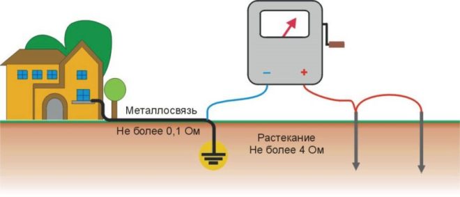
According to the Electrical Installation Rules (PUE), the ground loop must have a much lower resistance (no more than 4 ohms is allowed).
Now look, what is the principle of protective grounding. If some electrical device is faulty, that is, an insulation breakdown has occurred and a potential appeared on its body, and someone touched it, then the current from the surface of the device will go into the ground through a person, the path will look like “hand-body-leg ". This is a lethal danger, the current value of 100 mA causes irreversible processes.
Protective grounding minimizes this risk. Modern electrical appliances have an internal grounding connection between the plug and the body. When the device is connected to the outlet by means of a plug and as a result of damage to its body a potential appears, it will go into the ground along a grounding conductor with a low resistance.That is, the current will not go through a person with a resistance of 1000 ohms, but will run through a conductor, in which this value is much less.
That is why an important step in the arrangement of the electrical economy in our residential buildings is the measurement of the grounding resistance. We need 100% certainty that this value is below our human 1000 Ohms.
And remember that this is not a one-time procedure, the resistance must be measured periodically, and the circuit itself must be constantly maintained in good condition.
Checking the grounding of outlets
If you bought a house or apartment, and all the electrical part in the room was already installed before you, how to check the grounding in the outlet?
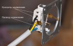
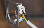
To begin with, we suggest that you make a visual inspection. Disconnect the entrance machine to the apartment and disassemble one outlet. It must have an appropriate terminal to which the grounding conductor is connected, as a rule, it has a yellow-green color version. If all of these are present, then the outlet is grounded. If you find only two wires - brown and blue (phase and zero), then the outlet has no protective ground.
At the same time, the presence of a yellow-green conductor does not mean that the grounding is working properly.
The efficiency of the circuit can be determined with a special device, without which no electrician can do, a multimeter. The algorithm for this check is as follows:
- Turn on the input circuit breaker in the switchboard, that is, voltage must be present in the sockets.
- Set the voltage measurement mode on the device.
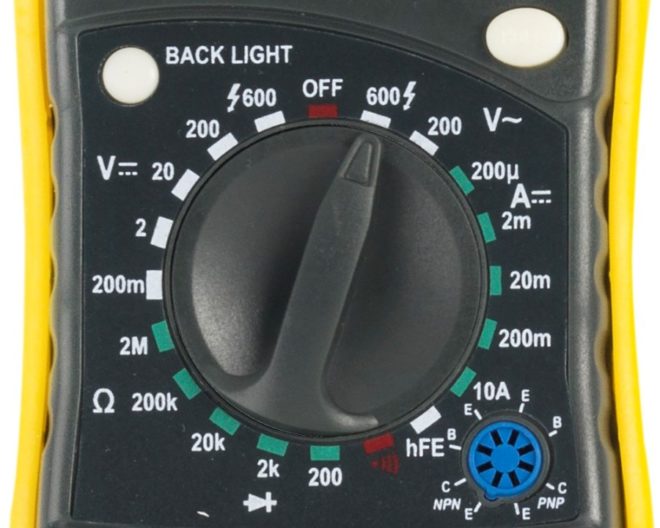
- Now you need to touch the phase and neutral contacts with the probes of the device and measure the voltage between them. The device should display a value of about 220 V.
- Make a similar measurement between the phase and grounding contacts. The measured voltage will be slightly different from the first value, but the very fact that some numbers appear on the screen indicates that there is grounding in the room. If there are no numbers on the screen of the device, it means that the ground loop is absent or it is in a faulty state.
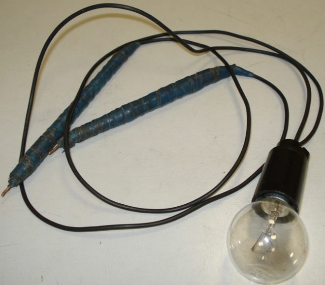
When there is no multimeter, you can check the operation of the circuit with a tester that is assembled by hand. You will need:
- cartridge;
- light bulb;
- wires;
- limit switches.
Electricians call such a tester "control light" or abbreviated "control". Touch one end probe to the phase contact, with the other touch the zero. The light should come on at the same time. Now transfer the end switch that you touched to zero to the antenna of the grounding contact. If the light comes on again, then the ground loop is operational. The lamp will not light if the protective earth is not working. A faint glow will indicate poor contour condition.
If an RCD is connected to the circuit under test, then during the test actions it may work, which means that the ground loop is operational.
Note! It may be such a situation that when the limit switches touch the phase and ground contacts, the lamp does not light up. Then try to move the probe to zero from the phase contact, perhaps during the connection of the outlet, zero with the phase were entangled.
Ideally, you should start checking actions by determining the phase contact in the switching device using an indicator screwdriver.
This method is clearly shown in the video:
The following indirect situations can also indicate a faulty or unconnected ground loop:
- a washing machine or water-heating boiler is electrocuted;
- noise is heard from the speakers when the stereo system is operating.
Measurements
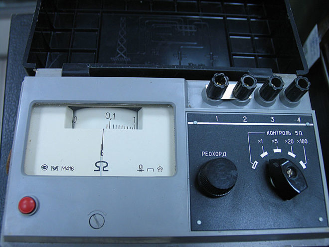
And yet, in the question of how to measure the grounding resistance, it is better to use not a multimeter, but a megohmmeter. The best option is considered to be a portable electrical measuring device M-416.Its work is based on a compensation measurement method, for this they use a potential electrode and an auxiliary ground electrode. Its measuring limits are from 0.1 to 1000 Ohm, the device can be operated at temperatures from -25 to +60 degrees, power is supplied by three 1.5 V batteries.
And now a step-by-step instruction of the whole process how to measure the resistance of the ground loop:
- Place the device on a horizontal flat surface.
- Now calibrate it. Select the "control" mode, press the red button and, while holding it, set the arrow to the "zero" position.
- There is also some resistance in the connecting wires between the terminals, in order to minimize this influence, place the device closer to the measured ground electrode.
- Select the required connection scheme. You can check the resistance roughly, for this, connect the leads with jumpers and connect the device in a three-clamp circuit. For the accuracy of measurements, the error that the connecting wires will give should be eliminated, that is, a jumper is removed between the terminals and a four-clamp connection scheme is used (by the way, it is drawn on the device cover).
- Drive the auxiliary electrode and the probe rod into the ground to a depth of at least 0.5 m, keep in mind that the soil must be solid and not loose. Use a sledgehammer to hammer, strikes should be straight, without swaying.
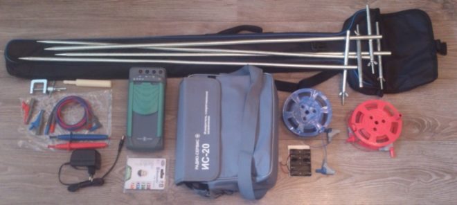
- Clean the place where you will connect the conductors to the ground electrode with a file from the paint. Use 1.5 mm copper conductors as conductors2... If you use a three-clamp circuit, then the file will act as a connecting probe between the ground electrode and the terminal, since a copper wire with a cross section of 2.5 mm is connected on the other side2.
- And now we turn directly to how to measure the grounding resistance. Select the range "x1" (that is, multiply by "1"). Press the red button and turn the knob to set the arrow to zero. For large resistances, it will be necessary to select a larger range ("x5" or "x20"). Since we have chosen the "x1" range, the figure on the scale will correspond to the measured resistance.
It is clear how the grounding measurement is carried out in the following video:
Some basic parameters and rules
No matter what time of year you take measurements, the readings must always comply with the following standards:
| For sources with single-phase voltage | For sources with three-phase voltage | Ground resistance value |
| 127 in | 220 V | 8 ohm |
| 220 V | 380 V | 4 ohm |
| 380 V | 660 in | 2 ohm |
It is recommended to take measurements under certain weather conditions, when the earth is considered the most dense.
The ideal time is mid-summer (when the ground is dry) and mid-winter (when the ground is very frozen).
Wet ground will greatly affect the current flow, therefore measurements taken in wet and humid weather in spring or autumn will be distorted.
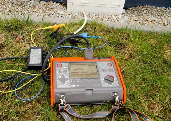
There is still a way to make measurements with a clamp meter, but the best option would be to contact a specialized service. The electrical laboratory will make all the necessary measurements and issue an appropriate protocol, which will indicate the location of the tests, the nature and resistivity of the soil, the measurement values with a seasonal correction factor.