We make a dimmer for home lighting with our own hands
Agree, sometimes there is a need to adjust the brightness of the lamp. Well, really, it is not always required that it shines at full power. If in the evening you have gathered with your family in the hall room for a conversation, dim lighting is enough. Why turn on the chandelier at full power, drive extra kilowatt-hours and overpay for electricity consumption. In this case, the dimmer helps out, otherwise this device is called a dimmer. With it, you can change the electrical power of the lamp and thereby adjust the brightness of the light. Many men, connoisseurs of electrical engineering and amateurs of radio electronics, assemble a dimmer with their own hands.
But here a completely logical question arises, why do you need a homemade dimmer, if you can go to an electrical goods store and buy a factory device? First, the price of a factory regulator is, frankly, not small. But this is not so bad. Sometimes there is a need to install a dimmer, for example, for a table lamp. And if you go to the store, it is not a fact that you will find a device of the right size for you so that you can shove it into such a lighting device. So the problem of assembling a dimmer at home with your own hands is still relevant and therefore we will devote this article to it.
Content
The main purpose and essence of the dimmer
A few words about what a dimmer is and why is it needed at all?
This device is electronic, designed to change electrical power with it. Most often, the brightness of the lighting fixtures is changed in this way. Works with incandescent bulbs and LEDs.
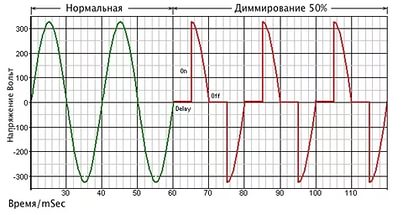
The electrical network supplies a current that is sinusoidal. In order for the brightness to change in the bulb, a cut-off sinusoid must be fed to it. It is possible to cut off the leading or trailing edge of the wave using thyristors installed in the dimmer circuit. This helps to reduce the voltage applied to the luminaire, which accordingly leads to a decrease in the power and brightness of the light.
Scheme elements
Let's start by deciding what elements we need for the dimmer circuit.
In fact, the circuits are quite simple and will not require any scarce parts; even an inexperienced radio amateur can figure them out.
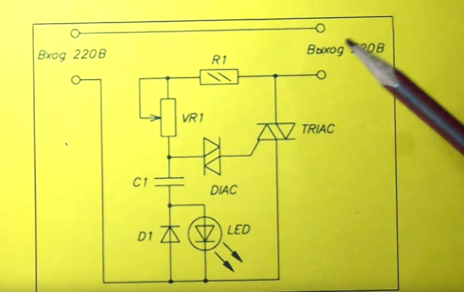
- Triac. This is a triode symmetric thyristor, in another way it is also called a triac (the name comes from the English language). It is a semiconductor device, which is a thyristor type. It is used for switching operations in 220 V electrical circuits. The triac has two main power outputs, to which the load is connected in series. When the triac is closed, there is no conductivity in it and the load is turned off. As soon as an unlocking signal is applied to it, conductivity appears between its electrodes and the load is turned on. Its main characteristic is the holding current. While a current in excess of this value flows through its electrodes, the triac remains open.
- Dinistor. It belongs to semiconductor devices, is a type of thyristor, and has bidirectional conductivity. If we consider the principle of its operation in more detail, then the dinistor is two diodes that are turned on towards each other. Dinistor is also called a diak in another way.
- Diode.This is an electronic element that, depending on which direction the electric current takes, has a different conductivity. It has two electrodes - a cathode and an anode. When forward voltage is applied to the diode, it is open; in the case of reverse voltage, the diode is closed.
- Non-polar capacitor. Their main difference from other capacitors is that they can be connected to an electrical circuit without observing polarity. Reversal of polarity is allowed during operation.
- Fixed and variable resistors. In electrical circuits, they are considered a passive element. A fixed resistor has a certain resistance, for a variable this value can change. Their main purpose is to convert current strength into voltage or vice versa voltage into current strength, absorb electrical energy, limit current. A variable resistor is also called a potentiometer, it has a movable tap-off contact, the so-called slider.
- LED for indicator. This is a semiconductor device that has an electron-hole junction. When an electric current is passed through it in a forward direction, it creates optical radiation.
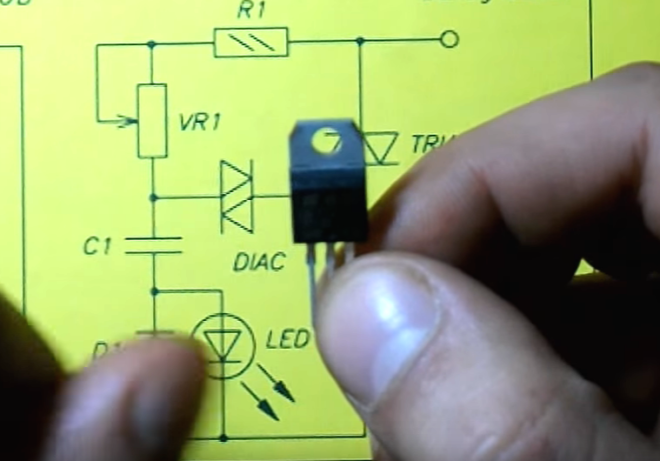
The triac dimmer circuit uses phase control. In this case, the main regulating element is a triac, the load power that can be connected to this circuit depends on its parameters. For example, if you use a VT 12-600 triac, you can regulate the load power up to 1 kW. If you want to make your dimmer for a more powerful load, then accordingly choose a triac with large parameters.
Principle of operation
Before making a dimmer with your own hands, let's figure out what the essence of its work is.
- When the circuit is connected to an electrical circuit, it receives an alternating voltage of 220 V from the network. When a positive half-period occurs in the voltage sine wave, a current begins to flow through the resistors and one of the diodes, due to which the capacitor is charged.
- As soon as the voltage reaches the parameter required for the breakdown of the dinistor, a current begins to flow through the dinistor and through the control electrode of the triac.
- This current helps the triac to open. Lamps that are connected in series with it are connected to the circuit and light up.
- As soon as the voltage sine wave passes through zero, the triac will close.
- When the sinusoidal voltage reaches the negative half-cycle, the whole process repeats in a similar manner.
- The opening moment of the triac is directly proportional to the value of the active resistance in the circuit. When this resistance is changed, the opening time of the triac can be changed in each half-cycle. This will smoothly change the power consumption of the light bulb and the brightness of its glow.
The principle of operation and the subsequent assembly of the device are described in more detail in this video:
Assembling the circuit
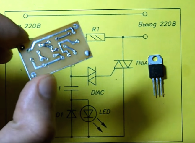
Now we come to assembling our dimmer. Keep in mind that the circuit can be hinged, that is, using connecting wires. But it will be better to use a PCB. For this purpose, you can take foil-coated textolite (35x25 mm size will be enough). A dimmer, assembled on a triac using a printed circuit board, allows you to minimize the size of the unit, it will have small dimensions, and this makes it possible to install it in place of a conventional switch.
Before starting work, stock up on rosin, solder, a soldering iron, wire cutters and connecting wires.
Further, the regulator circuit is assembled according to the following algorithm:
- Draw connection diagrams on the board. Drill holes for the leads of the connected elements. Using nitro paint, draw tracks on the diagram, and also determine the location of the mounting pads for soldering.
- Next, the board must be etched. Prepare ferric chloride solution.Take the dishes so that the board does not lie tightly on the bottom, but with its corners, as it were, rested against its walls. During etching, turn the board periodically and stir the solution. In the case when this must be done quickly, warm the solution to a temperature of 50-60 degrees.
- The next stage is tinning the board and rinsing it with alcohol (it is undesirable to use acetone).
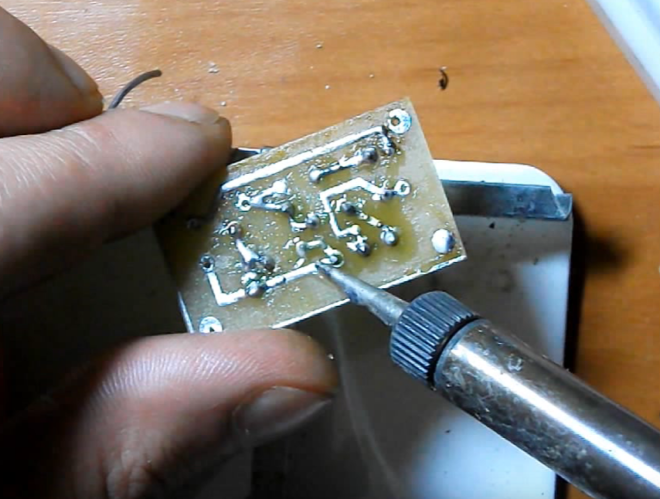
- Install the elements into the holes made, cut off the excess ends and use a soldering iron to solder all the contacts.
- Solder the potentiometer using the connecting wires.
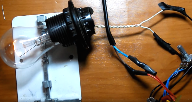
- And now the assembled dimmer circuit is being tested for incandescent lamps.
- Plug in the light bulb, plug in the circuit and turn the potentiometer knob. If everything is assembled correctly, then the brightness of the lamp should change.
Connection
As a rule, dimmers are installed in place of switches. That is, it is mounted on a phase break in series with the load. This, by the way, is very important, as well as when connecting the switch. In no case do not mix up the phase and zero, if you set the dimmer to break the zero, the electronic circuit will fail. In order to avoid mistakes, before installation, using an indicator screwdriver, make sure exactly - where is your phase, and where is zero.
Further, the algorithm is as follows:
- De-energize the workplace by disconnecting the input machine for the room or apartment.
- Remove the switch from the mounting box.
- Apply voltage and accurately determine the phase and zero on the disconnected wires. Mark the detected phase in some way (with a marker or tape).
- Disconnect the input power again. Connect the input terminals of the dimmer to the phase wire, the output terminals are connected to the load. For factory regulators, the terminals are marked, in this case, the connection must be made according to the marking. But for dimmers there is no fundamental difference, so the phase connection can be arbitrary.
- A DIY dimmer for 220 V LED lamps is installed in the same way. The only fundamental difference is that it must be installed before the controller of these lamps. That is, the output from the dimmer goes to the input of the controller.
The dimmer that you assembled with your own hands can be used not only as a power regulator on a triac for lighting. With it, you can change the speed of the exhaust fan or adjust the temperature of the soldering iron tip. So if you are friends with electronics, you are quite capable of making a triac regulator. It may not make your life much easier, but the fact that you created it yourself is already good.