Zero and phase in electrics - the purpose of the phase and neutral wires

The owner of an apartment or a private house, who decides to do any procedure related to electricity, whether it is installing an outlet or a switch, hanging a chandelier or a wall lamp, invariably faces the need to determine where the phase and neutral wires are located at the place of work, as well as the grounding cable. This is necessary in order to properly connect the mounted element, as well as to avoid accidental electric shock. If you have some experience with electricity, then this question will not confuse you, but for a beginner it can be a serious problem. In this article, we will figure out what phase and zero are in electrics, and tell you how to find these cables in a circuit, distinguishing them from each other.
Content
What is the difference between a phase conductor and a zero conductor?
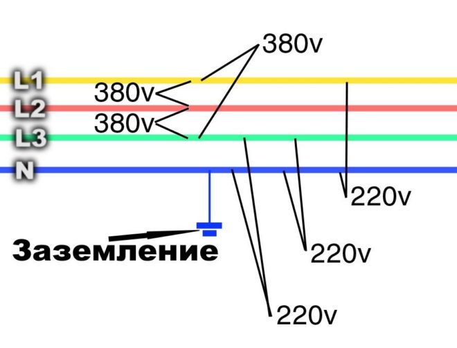
The purpose of the phase cable is to supply electrical energy to the desired location. If we talk about a three-phase power grid, then there are three current feeds for the only neutral wire (neutral). This is due to the fact that the flow of electrons in a circuit of this type has a phase shift of 120 degrees, and the presence of one neutral cable in it is quite sufficient. The potential difference on the phase wire is 220V, while the zero, like the ground wire, is not energized. On a pair of phase conductors, the voltage value is 380 V.
Line cables are designed to connect the load phase to the generator phase. The purpose of the neutral wire (working zero) is to connect the load zeroes and the generator. From the generator, the flow of electrons moves to the load along linear conductors, and its reverse movement occurs along zero cables.
The neutral wire, as mentioned above, is not energized. This conductor has a protective function.
The purpose of the neutral wire is to create a circuit with a low resistance index, so that in the event of a short circuit, the current is sufficient for the immediate operation of the emergency shutdown device.
Thus, damage to the installation will be followed by a quick disconnection from the mains.
In modern wiring, the neutral conductor sheath is blue or light blue. In old circuits, the working neutral wire (neutral) is combined with the protective one. This cable has a yellow-green coating.
Depending on the purpose of the power transmission line, it may have:
- Solidly grounded neutral cable.
- Insulated neutral wire.
- Effectively grounded zero.
The first type of line is increasingly used in the arrangement of modern residential buildings.
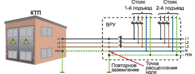
In order for such a network to function correctly, energy for it is generated by three-phase generators and is also delivered along three high-voltage phase conductors. Working zero, which is the fourth wire, is supplied from the same generator set.
Clearly about the difference between phase and zero in the video:
What is a grounding cable for?
Grounding is provided in all modern electrical household appliances. It helps to reduce the amount of current to a level that is safe for health by redirecting most of the flow of electrons to the ground and protecting a person who touches the device from electrical shock.Also, grounding devices are an integral part of lightning rods on buildings - through them, a powerful electric charge from the external environment goes into the ground, without harming people and animals, without causing a fire.
The question - how to identify the ground wire - could be answered: by the yellow-green sheath, but the color coding, unfortunately, is often not followed. It also happens that an electrician who does not have sufficient experience confuses a phase cable with a zero one, or even connects two phases at once.

To avoid such troubles, you need to be able to distinguish the conductors not only by the color of the shell, but also in other ways that guarantee the correct result.
Household wiring: find zero and phase
You can install at home where which wire is located in different ways. We will analyze only the most common and accessible to almost any person: using an ordinary light bulb, an indicator screwdriver and a tester (multimeter).
About the color coding of phase, neutral and ground wires in the video:
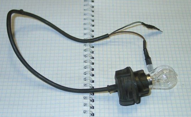
Checking with an electric lamp
Before starting such a test, you need to assemble a test device using a light bulb. To do this, it should be screwed into a cartridge of a suitable diameter, and then fixed on the wire terminal, removing the insulation from their ends with a stripper or a regular knife. Then the lamp conductors must be applied alternately to the tested conductors. When the lamp comes on, it will mean that you have found a phase wire. If the cable is checked for two cores, it is already clear that the second will be zero.
Checking with an indicator screwdriver
The indicator screwdriver is a good helper in electrical work. This inexpensive tool is based on the principle of a capacitive current flowing through the indicator housing. It includes the following main elements:
- A metal tip, shaped like a flat screwdriver, that is attached to the wires for testing.
- A neon lamp that lights up when current passes through it and thus signals the phase potential.
- A resistor for limiting the amount of electric current, which protects the device from burning under the influence of a powerful flow of electrons.
- A contact pad that allows you to create a circuit when touched.
Professional electricians use more expensive LED indicators with two built-in batteries in their work, but a simple Chinese-made device is quite accessible to anyone and should be available to every owner of the house.
If you check the presence of voltage on the wire with this device in daylight, then you will have to look more closely during work, since the glow of the signal lamp will be poorly noticeable.
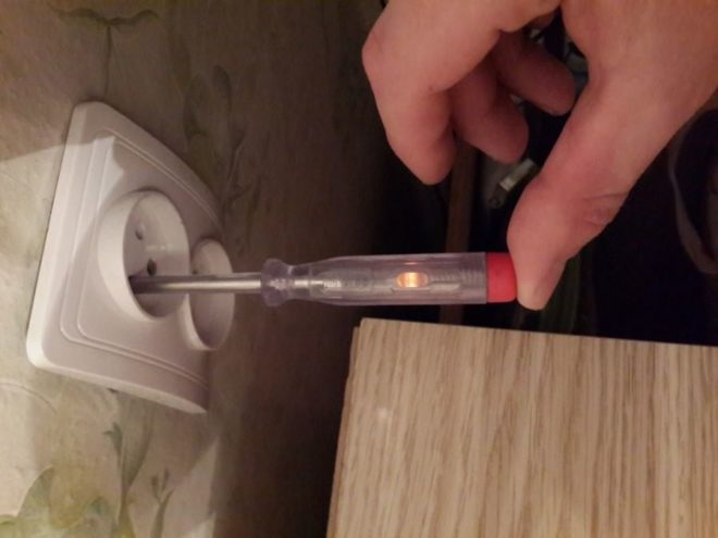
When the tip of a screwdriver touches the phase contact, the indicator lights up. In this case, it should not glow either at the protective zero or on the ground, otherwise it can be concluded that there are problems in the connection diagram.
When using this indicator, be careful not to inadvertently touch a live wire with your hand.
About phase detection clearly on the video:
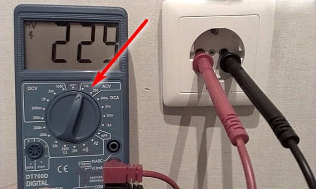
Checking with a multimeter
To determine the phase using a home tester, the device must be put in the voltmeter mode and the voltage between the contacts must be measured in pairs. Between the phase and any other wire, this indicator should be 220 V, and applying the probes to ground and protective zero should indicate the absence of voltage.
Conclusion
In this material, we answered in detail the question of what the phase and zero are in modern electrics, what they are for, and also figured out in what ways you can determine where the phase conductor is located in the wiring.Which of these methods is preferable is up to you, but remember that the issue of determining the phase, zero and ground is very important. Incorrect test results can cause the appliances to burn out when connected, or worse, cause an electric shock.


